Category: Port Forwarding


In the previous post PART 1  we explored the ways to make the local IP address of PC/ESP8266 STATIC.

In this part 2 we shall see how to make your Dynamic Public IP as STATIC using NO-IP account & then Port forward to the server started on port 350 of ESP.

PORT FORWARDING

First let us do the PORT FORWARD  settings.

For this , type in your Router’s Gateway IP in the browser & log in to Router’s Settings.Here my Router’s gateway is 192.168.1.1

The PORT Forwarding is done under VIRTUAL SERVER.

For different Router , you can check out this excellent link which guides settings for almost all types of Routers in the World.

https://portforward.com/router.htm

In my case the VIRTUAL SERVER is under ADVANCED —> NAT


image1

Under Virtual Server feed in the WAN & LAN ports as 350.

Under LAN IP feed in the static IP of our ESP8266.Here it is 192.168.1.10 which we made static as described in part 1.

Once the APPLY CHANGES button is clicked , the entry appears under Forwarding Table.

Image 2


WINDOWS FIREWALL SETTINGS


Next is the Windows firewall settings to allow communication through port 350.

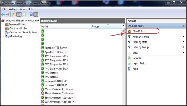
Open Windows Firewall with Advanced Security.

Click on Inbound Rules & then New Rule.


Image 3


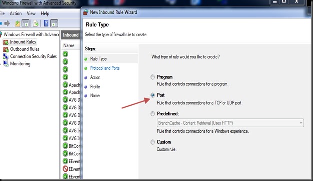
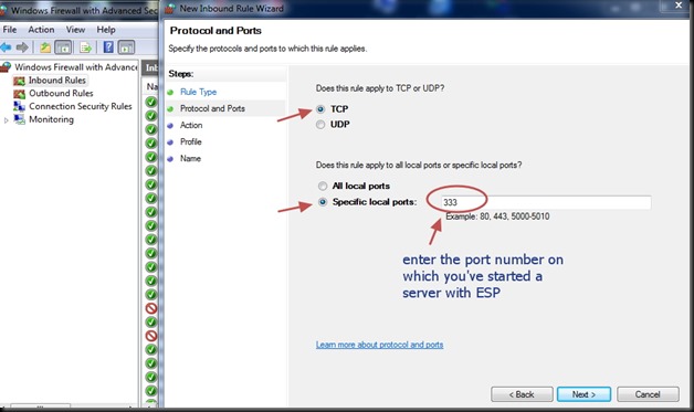
Select Rule Type as PORT.

protocol as TCP.


Image 4

Under Action select “Allow the Connection”

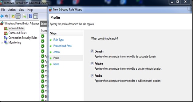
& tick mark all under the Profile.

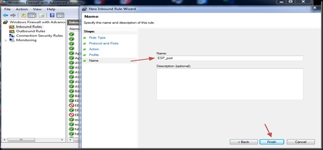
Provide a Name for the Rule & save it.

Image 5


START SERVER ON ESP8266

Now open the Putty window where you’ve connected ESP8266 ( refer part 1 for details)

Before starting server , issue the command

AT+CIPMUX=1

Then start the server on port 350 using

AT+CIPSERVER=1,350

Image 111

Now the Server starts listening on PORT 350.


Convert Public IP to STATIC

The external world communicates with your ESP server using the Public IP of your Network.This IP is generally DYNAMIC which means it changes on every boot of your Router.

To make it STATIC we shall use a service called NO-IP which converts your public IP to a Domain name & follows the changes.

Visit www.noip.com

Sign up by providing your EMAIL.

Image 6

LOG IN  your NO-IP account.

Under Dynamic DNS click on ADD HOSTNAME.

Image 7

Enter the host name, for e.g , as   testmyiot  & from the dropdown select a domain , say, ddns.net.

Now your new host name is

testmyiot.ddns.net


Image 8

Next , click on Device Configuration Assistant.

Image 9


Under the dropdown select the host name we created , testmyiot.ddns.net


Image 10

Next step is to fill in the Device details.

Device type is SERVER

Device Brand is WEB SERVER

Router make – select your router name .If not found in list then select other

& then enter Router type as Home.

Image 12

On the Next window answer NO

We shall come back to this window shortly after setting the Router for NO-IP.

Image 13


On the next window , before clicking YES to log in device, go to the Router settings in browser where you typed in 192.168.1.1

Image 14


Click on SERVICE & then DDNS.

Most of the Routers support NO-IP & is listed on the drop down.

Select NO-IP

Image 15

Feed in the Host Name as testmyiot.ddns.net

Provide the email & password you used to create the NO-IP account.

Image 17

Click on ADD to save to DDNS Table of Router.

Now go back to your NO-IP account window.

Click YES to log in device.

Image 18

On next window click on TEST CONNECTION

Image 19

After a short time you should see SUCCESS.

Now you’re done with DDNS settings.You need not go further to Port forward tab, as we’ve already done it.

Image 20


Following is the procedure , in case your Router doesn’t support NO-IP .

If you do not see NO-IP under drop down of DDNS settings of Router,

go back to your NO-IP account & click YES to the question “Is there a computer always running on your Network?”.


Image 22


You’ll be taken to next window to download DUC.

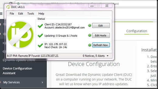
DUC- Dynamic Update Client is a software which runs in the background of your PC to follow your public IP.

Download it & install.

Image 23

Before FINISH ensure to tick mark “Run DUC in the background”

Image 24

Now you’ll be asked to login your NO-IP account again

Image 25

Once you log in, the following windows appear.

Select the host name you created & click save.

Image 26

Now you can see all TICK marks in the DUC window.

DUC runs in the background & follows your public IP to the domain name you created.

Image 28


You can test the access to ESP server now from a distant PC.

From anywhere in the world , make open a PUTTY window.

Select RAW & feed in the host name testmyiot.ddns.net & port as 350.

Image 29

You get CONNECTED to the ESP server


Watch this demo video :


cooltext753793315   cooltext753790696

This post is all about converting your device address in Network to STATIC & establish PORT FORWARDING.

For IOT projects it is easy to test in local setup using  the LAN IP starting with 192.x.x.x .But from outside world this IP cannot be reached.Here I will walk you through the steps to contact the local IP from outside world.This procedure is a major step needed in IOT projects  , without which external control is not possible.

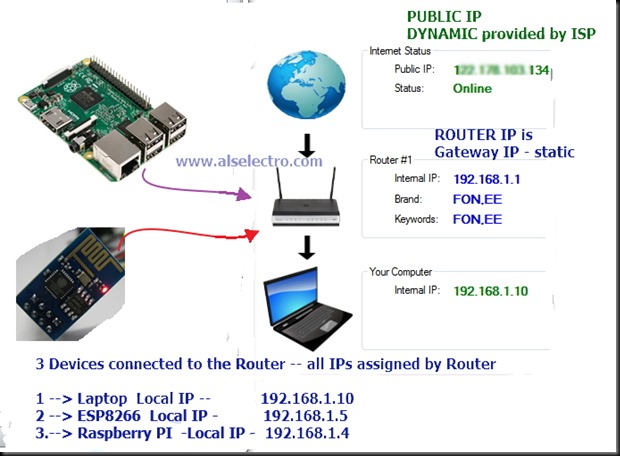
Following is the setup of my Network. A ROUTER is on the top of the network for which the Internet Service Provider is Airtel . The Router is WIFI enabled so that I can connect multiple devices wirelessly.

Total 3 devices are connected to the Router as shown below.


setup_ok


On switching on the power , the Router (DHCP enabled) assigns local IP addresses to all the devices connected.The IP address assigned is DYNAMIC which means , it changes every time I switch on the Router.

There are two types of IP addresses: STATIC & DYNAMIC

STATIC addresses are just that – unchanging

Dynamic IP addresses are assigned on-the-fly & keeps on changing by every reboot.

Because most home users tend to turn their computers off, even broadband connections, such as DSL and cable, continue to use dynamic addresses. If your computer is off, you don’t need an IP address so someone else might get to use it.

Each time you connect to the internet, your ISP assigns you an IP address to use. This IP address is the Public IP which others use to communicate to your PC.This IP address is DYNAMIC which changes every time you newly connect to web.

The next time you connect, you might get a different address. If you’re only connecting out to the internet, that’s all you need.

If you expect people to connect in, say you want to run a web server that you want people to be able to find and visit, you’ll most likely need a STATIC IP address. A static IP is assigned by your ISP at an extra cost which is unnecessary for a home network.

In this post I shall explain the ways of changing the LOCAL IP address  as well as the PUBLIC IP address to STATTIC.Suppose you run a web server on your ESP or Raspberry PI & wish to connect from external world.It will work only for the first time , as you use Dynamic IP to communicate.

Next time you power up , the IP address might have changed.So using a STATIC IP is a must .


SETTING the Local IP of PC / Laptop to STATIC :


In my network the PC assigned a Dynamic IP of  192.168.1.10

Run –> CMD –> ipconfig /all       reveals the  address details as seen below :

ipconfig


Here you can see the Default Gateway is 192.168.1.1 which is the IP of the Router .To port forward settings we need to use this IP on a browser to enter the settings , which we will see later in the post.

Local IP assigned to the PC is the IPV4 address 192.168.1.10

Let us change this to STATIC now.

Open the CONTROL PANEL –> NETWORK and Internet  –> Network and Sharing center

Click on “Change adapter settings”

Image 10


Right Click on the Network connection & select Properties

Image 11


Select the Internet Protocol Version 4 & double click on it.

Image 12

Now you see the following screen where selection is done by default to obtain IP automatically.

Change this selection o “USE the following IP address “ & enter the IP as 192.168.1.150

The first three bytes must match that of the default gateway address which is 192.168.1.1

The last byte can be assigned at your will , within the IP range allowed by the router.

Here I change the IP to 192.168.1.150.  Note that only the last byte I’ve changed.

Subnet mask & Default gateway are entered as seen in the ipconfig /all window above.


Image 13


DNS server address also changed as seen in the screen shot below

Image 14

Image 15

Reboot your PC to see the changes effective.

Now the IP address of my PC will be 192.168.1.150 & remains STATIC even after reboot.

The above task can also be done automatically by a trial software :

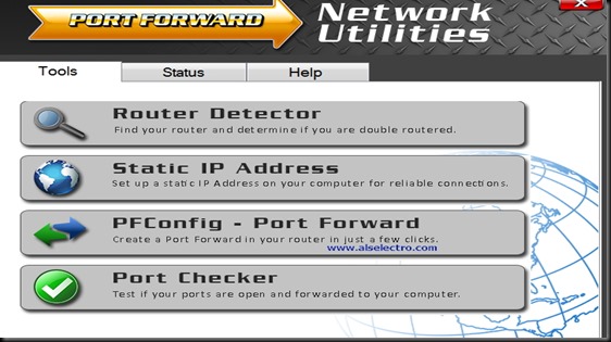
PF_1


You can download the trial version here :

http://portforward.com/store/download-instructions/pfconfig/

The trial version allows all other tools except port forwarding.Open the tool & click on STATIC IP Address & follow the guidelines to fix your PC’s IP as STATIC.


STATIC IP for other devices ESP & Raspberry PI:


For making the Raspberry Pi’s Local IP to STATIC you can follow this blog :

https://www.modmypi.com/blog/tutorial-how-to-give-your-raspberry-pi-a-static-ip-address


Regarding the IP of ESP8266 we need not change anything.Once the STATION IP is assigned to ESP8266 , the module remembers the Access Point it has connected & the STA IP assigned .

or issue the command

AT+CIPSTA=”192.168.1.5”

Image 16

The ESP module remembers the Access Point it has joined with & the IP till you quit the AP.

But on Reset it seems to get changed.

The only way to assign STATIC IP to ESP module is through the Router settings.

In your browser type in the IP address of your Gateway , here it is 192.168.1.1

Under LAN setup look out for DHCP settings.

In latest Routers you see a setting called DHCP RESERVATIONS.

In the IP Address field, type the IP address to assign to the computer or server.
Choose an IP address from the router’s LAN subnet, such as 192.168.1.x.

Type the MAC address of the ESP MODULE server.
As the ESP has already joined the AP, it  is already on your network, you can copy its MAC address from the Attached Devices screen and paste it here.

Here I will show an example of setting the Static IP in DHCP Reservation under BEETEL Router

In almost all the Routers the settings are the same.Just look out for the wordings Open-mouthed smileHCP RESERVATION” or “DHCP STATIC “ under the LAN setup.


dhcp1


Under DHCP STATIC tab , enter the IP address you want to fix for the ESP module

dhcp2


Feed in the MAC ADDRESS of the ESP device.

dhcp3

You can learn the MAC address from the AT command AT+CIFSR of ESP module.

dhcp4

The MAC address to be entered without any special character like colon.Please check out your Router settings for entering the MAC address (generally given near the MAC address box , how to feed in the address).

dhcp5

Click on ADD to save the settings

dhcp6

Now RESET or power back the ESP module.

The IP address will be the same for ever.The Router will always assign the IP you’ve set for the ESP module.

dhcp7


In a  D-Link router, it is under  the setup.Go to Setup / Network settings / DHCP reservation. You can then ask the router to give a given MAC address a fixed IP address.
Alternatively, the ESP can request a certain IP address from the router which we’ve seen in the example of Beetel Router above.

Now that the STATIC IP is assigned, let us see the methods of PORT FORWARDING & converting your public IP to STATIC using NO-IP account in PART 2.


In the previous post part-1 I explained the initial setup of starting a Server on PC on a port , setting the Windows firewall to allow the port for external communication , PORT FORWARDING set up in the Router config, etc..

https://alselectro.wordpress.com/2016/09/25/gsm-connecting-to-a-server-on-a-port-by-tcpip-part-1/

In this part 2 I’ll show a practical demo of sending Temperature data to the Server.

As given in part 1 , start a server on distant PC on port 350 & do the port forwarding settings in Router config as explained.

A LM35 sensor is connected to pin A0 of Arduino & a GSM SIM900A is connected to pins 7 , 8 , Gnd of Arduino. As Soft Serial library is used in the code , pins 7 & 8 are declared as soft Rx & Tx.

The Rx pin goes to Tx of GSM , Tx connected to Rx of GSM , GND is made common.An external power source of 12v 1A is used for the GSM.

Download the Arduino code HERE

————————————-

#include <SoftwareSerial.h>
SoftwareSerial myGsm(7,8);
float temp;
int tempPin = 0;
void setup()
{
myGsm.begin(9600);
Serial.begin(9600);
delay(500);

myGsm.println(“AT+CIPSHUT”);
delay(1000);
printSerialData();

myGsm.println(“AT+CIPMUX=0”);
delay(2000);
printSerialData();

myGsm.println(“AT+CGATT=1”);
delay(1000);
printSerialData();

myGsm.println(“AT+CSTT=\”bsnlnet\”,\”\”,\”\””);//setting the APN,username & password
delay(5000);
printSerialData();

myGsm.println();
myGsm.println(“AT+CIICR”);
delay(6000);
printSerialData();

myGsm.println(“AT+CIFSR”); //get IP address
delay(2000);
printSerialData();

myGsm.println(“AT+CIPSTART=\”TCP\”,\”122.178.80.228\”,\”350\””);
delay(5000);
printSerialData();
delay(5000);

myGsm.println(“AT+CIPSEND”);
delay(2000);
printSerialData();

sendtemp();
delay(3000);
myGsm.println(“AT+CIPCLOSE”);
printSerialData();

myGsm.println(“AT+CIPSHUT”);
delay(1000);
printSerialData();
}

void loop()
{
}

void printSerialData()
{
while(myGsm.available()!=0)
Serial.write(myGsm.read());
}


void sendtemp()
{
temp = analogRead(tempPin);
temp = temp * 0.48828125;
Serial.print(“TEMPERATURE = “);
Serial.print(temp);
Serial.print(“*C”);
Serial.println();
delay(5000);
myGsm.println(temp);
delay(3000);
printSerialData();
myGsm.write(0x1A);
delay(3000);
printSerialData();

}

———————————————-

The Analog pin A0 is assigned as tempPin to read the LM 35 sensor data.

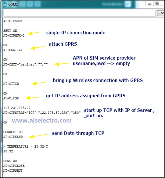
Initially any previous IP connection is SHUT  using the command

AT+CIPSHUT

This is essential to start a fresh TCP/IP comnnection.

Single IP connection mode is set by

AT+CIPMUX=0

GPRS is attached using

AT+CGATT=1

Task is started with the command

AT+CSTT=”APN”,”USER NAME”,”PASSWORD”

The Access Point Name of the mobile service provider can be known  by placing the SIM on your Android mobile. It’s shown under

Settings  –> More..  –>  Cellular Networks –> Access Point Names

In my case the APN is bsnlnet , user name & password are empty

AT+CSTT=”bsnlnet”,””,””


Then we bring up the Wireless connection with GPRS using

AT+CIICR

This takes a little moment , so a delay of 6 secs is a must in the code.

The IP address assigned by GPRS is obtained by

AT+CIFSR

Now we start up TCP connection with Server IP address & Port number of distant server

AT+CIPSTART=”TCP”,”122.178.80.228″,”350”

Once the connection is established , we send data using

AT+CIPSEND

A CTRL+Z is required to send data which is executed using hex 1A


Upload the code to Arduino & open the Serial monitor to watch the AT commands executed

tcp_list


Following is the screen shot at the Server side.


Image 3


cooltext753793315

This tutorial is of 2 parts.

First part explains the following :

–Starting a Server on your PC  & start listening on a port (say 350) . For this we use SOCKET TEST or HERCULES software

— Once the port is listening , we test communication locally using PuTty

— Windows Firewall setting has to be done for a NEW INBOUND RULE allowing port 350 for communication.

— For connecting to this port from external world , PORT FORWARDING to be done in Router’s Virtual Server setting so that any contact to the public IP is routed to the PORT 350 .


Second part is practical demo using GSM SIM900 or ESP8266 with Arduino.


The following picture shows my simple home network connections.A BINATONE make Router is used to connect to the Internet provider Airtel Broadband.The IP address of the Router is

192.168.1.1

which is the Gateway IP address used to access the settings on Router.My Laptop is connected over WIFI to this Router.The Router assigns a local IP address to my PC which is

192.168.1.150

Apart from these, the Internet Provider assigns a Public IP to my Network which is

122.178.80.228

This is the IP by which external world can contact my network.

Note that all these IP addresses are DYNAMIC & changes every time I power up the Router.

In another post I’ll explain how to make these IP addresses STATIC , so that the IP remain the same always.

set1


All the Network Tools I’ve used for this demo can be downloaded HERE.

Let us start  a server on port 350 using the SOCKET TEST tool.

This tool allows us to start a server easily.Click on the SERVER Tab & then feed in the port number where you want to listen.

Click on START LISTENING.

soc1

Now the server is up & running.It starts listening on port 350.

Remember to avoid the standard ports like 80 ( http) , 21 (FTP), 23 (TELNET), 22 (SSH) ,etc which are well known ports ,pre assigned for the particular protocol.

The dynamic range of port number you can assign goes up to 65535 or 2^16-1 (16 bits).

The IP address of the router can be known from the command window

RUN –> CMD –> ipconfig

The Default Gateway IP is the address of the Router.

RUN1


LOCAL TESTING TOOLS (optional)


Once the port is assigned for the server , you can use the ADVANCED PORT SCANNER tool to verify the port on the particular IP.

In the screen shot below you can see that the port number 350 is discovered as a TCP Server port on my PC whose local IP is 192.168.1.150


port_scanner

While the port scanner is scanning , you get messages on your SOCKET TEST window.

Here you can see the Port scanner software connecting to the port & then disconnecting after scanning.

port_message


Alternatively you can use a PUTTY serial port tool to test local communication.

Select the connection type as RAW & provide the host IP which is 192.168.1.150 & thtn the port number 350

putty1

Click on open , to see the New client connection on the Socket test window.

putty4


Now you can test two way communication between  socket test (server) & putty ( client).

putty2


WINDOWS FIREWALL SETTINGS


The Windows Firewall settings has to be done to allow the port 350 to listen from outside.

Open the Windows Firewall & Advanced Security window.

Click on Inbound Rules & then New Rule.

windows1


Select the Rule Type as PORT & in the next screen select protocol as TCP.

Under Specified local ports feed the port number as 350

windows2


Under Action window select Allow the Connection

Next window is Profile window , here tick mark all – Domain,Public & Private.

Provide a name to the Rule & save it.

Now your PORT 350 is allowed to listen by the Windows Firewall.

windows3


PORT FORWARDING

This step is final where you redirect the incoming request to the port number of local IP where the server is started.

Here my local PC’s IP is 192.168.1.150   &  server is started on port 350.

Anyone from external world connecting to my public IP has to be directed to the port 350 on local IP 192.168.1.150.

This is called PORT FORWARDING , which is very widely used in CCTV Remote viewing & in Gaming.

The setting has to be done in your Router.

Type in the Gateway IP of your Router , here it is 192.168.1.1 , on your browser & provide the user name & password.

Here is an excellent website showing all screen shots of almost all Routers in the world

https://portforward.com/router.htm


Mine is BINATONE Router.

You’ve to search for something called VIRTUAL SERVER on the router setting.


ROUTER1


For my Router it’s hidden under ADVANCED SETUP –> NAT –> VIRTUAL SERVER

For more details you can visit the above portforward link

Create a new Virtual server listing by entering the

— Port number , which is 350 .Enter same number at all fields like start & stop.

— Local IP address , here you provide the IP where server is started , 192.168.1.150

— save the listing

router3


Once saved , the port number 350 is open to outside world.

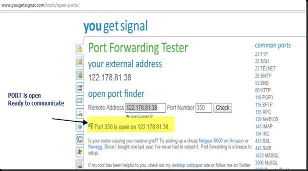
Online port open test tools are available

www.canyouseeme.org

www.yougetsignal.com


Once you open the link , your public IP will be automatically shown.

Fill in the PORT number to be checked & click on CHECK button.

If you see SUCCESS , then you’re done with PORT FORWARDING


canyou1


port_open


Following is the list of AT commands used by the GSM SIM900A to contact the server.

This is for part 2 of the post.PART 2 LINK HERE

gsm1

gsm2

cooltext753793315   cooltext753790696

After struggling for nearly a week with MTS dongle , finally I found an excellent solution to enable PORT FORWARDING.

HUAWEI POWER FI  E8221 model dongle  is the solution I found.This dongle accepts any data SIM for internet connectivity & we can create a WIFI HOTSPOT with this dongle to connect max. of 10 devices.

Further it has got a VIRTUAL SERVER setting tab in the configuration , thus enabling Port forwarding.

There is no need of an external Router like TP-LINK (which I used with MTS , as seen in my previous post).

1

I’ve inserted a BSNL DATA SIM into the HUAWEI dongle for Internet connection.

The DEFAULT GATEWAY IP address while using Huawei is 192.168.8.1

This can also be found by opening CMD in Windows search bar & then typing the command IPCONFIG /ALL

Typing this Gateway address in the browser , you get the HUAWEI CONFIGURATION window.Here the service provider (for me BSNL ) name is displayed with connection status.

Image 1

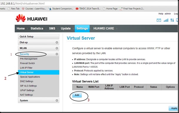
Click on CONNECTION SETTINGS seen below the “Connected” status.

On left pane , under SECURITY tab select the VIRTUAL SERVER.

Before clicking the ADD button under VIRTUAL SERVER LIST , we’ve to configure the ESP module & start a SERVER on port 333.

Image 2

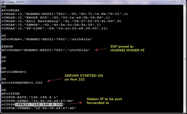
The ESP 8266 module is connected to PC through USB-TTL board & the COM port allotted in my PC is COM 48 .

I’m using PUTTY terminal software to communicate with this COM port.

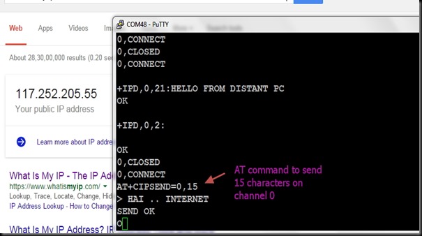
Following is the screen shot on which you can see the AT commands used to connect ESP with HUAWEI on WIFI , & starting a server on port 333.

The selection of port is random.You can select any port within 65536 , except the standard ports like 80 (HTTP) ,  21 (FTP), 23 (TELNET) ,etc..

AT+CWLAP   – to list the surrounding Access Points near ESP module

AT+CWJAP=”ssid”,”password”   – to join the AP using the SSID name & its password.

AT+CIPMUX=1   — to enable Multiple connections before starting server

AT+CIPSERVER=1,333   –  to start a server on port 333

AT+CIFSR  –  displays the IP address . STAIP is the IP address we need to port forward.

Image 3

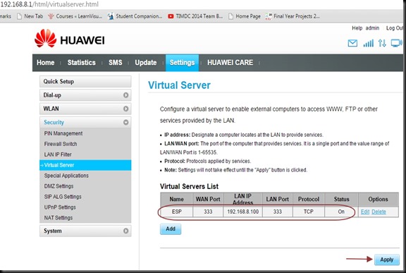
After starting the server on ESP8266 , we need to port forward under the HUAWEI configuration.

Click on the ADD button , seen under VIRTUAL SERVER LIST.

Fill in details as below :

Name  : ESP

WAN Port : 333

LAN IP   : 192.168.8.100

LAN Port  ; 333

Protocol : TCP

Status  : ON

Finally click on APPLY.

Image 4

Needless to say , you’ve to apply an INBOUND RULE on Windows Firewall settings to allow this port 333 . (check the previous post on how to do this).

The external world can contact this ESP only through the EXTERNAL IP address.To know the IP , just type in WHAT IS MY IP on Google .In my case it is 117.252.205.55

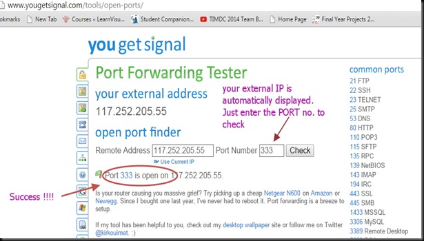
To confirm that the PORT 33 is open & listening , visit the online tool www.yougetsignal.com

You need to test this on the PC where you’ve connected the ESP module.

The external IP will be automatically displayed.You just  type in the port no. to verify.

Following screen shot shows that my port 333 is open

Image 6

Now we’re all set to contact ESP from outside World.

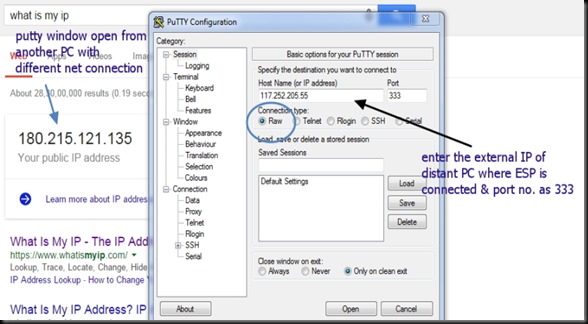
From a distant PC with different Internet connection , open a PUTTY terminal.

Select RAW as Connection type & type in the IP 117.252.205.55  & port no. as 333.

Following screen shot shows the PUTTY terminal which I’ve opened on a different PC with a different IP.

Image 5

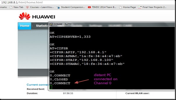
On clicking OPEN button , the ESP Terminal at the other end will respond with

0,CONNECT

This means a connection established on channel 0.

Image 8

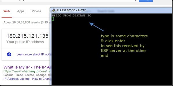
Now type in some characters on the distant PC terminal.

newip2

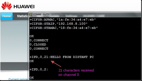
The ESP terminal responds with

+IPD,0,21:characters received

which indicates , it has received 21 characters on channel 0.

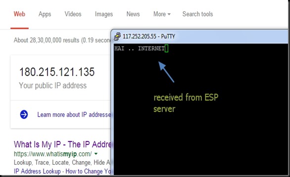
The screen shots with HUAWEI symbol (IP 117.252.205.55 ) is that of TERMINAL where ESP module is connected & the screen shot of distant PC is shown with the IP address 180.215.121.135

Image 9

To send characters from ESP , use the AT command :

AT+CIPSEND=0,15

This indicates that you want to send 15 characters on channel 0.

The ESP will respond with a > symbol & waits till you type 15 characters.

Image 10

The distant PC now receives the 15 characters you typed inside ESP terminal.

newip3

Hence a two communication is established with ESP Terminal & a PC from anywhere in the world.This opens the door for INTERNET OF THINGS where you can control the devices connected to ESP from anywhere in the World.

WATCH THIS VIDEO :

cooltext753793315    cooltext753790696

In the previous post we’ve seen the ways to control the ESP8266 WIFI module from anywhere in the world.The key to success depends on the PORT FORWARDING , where we route the contact on particular port to the local IP address of the WIFI module.

Nowadays USB dongles are used widely for internet access .This post will help you troubleshoot PORT FORWARDING.

Following is the SETUP diagram .

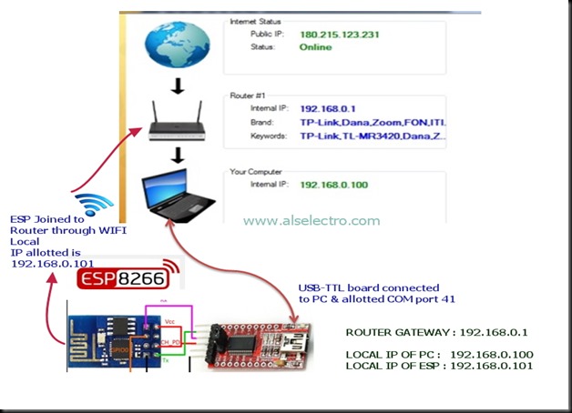
TPLINK ROUTER is on the top of the NETWORK. An MTS USB dongle is plugged to TPLINK Router (model TL-MR 3420 with 3G/4G support).

A Laptop is connected to TPLINK Router on Ethernet using RJ45 cable.

A USB to TTL board is connected to PC on which the ESP 8266 module is wired.

The ESP module is linked to TPLINK Router on WIFI using the AT Command AT+CWJAP=”SSID”,”password”


ip8

On switching ON the ROUTER , it assigns LOCAL IP address to the modules connected to it either on RJ45 (wired) or on WIFI.

In our set up the LAPTOP which is connected by wire is assigned 192.168.0.100

& the ESP module which is connected on WIFI is assigned 192.168.0.101.

Note that the allotment of address is on first come basis.When you power off & on the Router again , this allotment may vary.

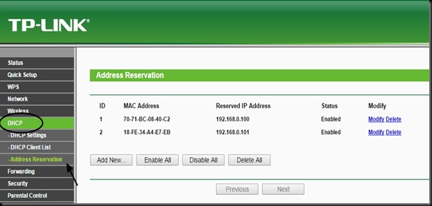
You can RESERVE the address by selecting the DHCP tab of TPLINK configuration.Here select

Address Reservation & then feed in the MAC address of the devices you’ve connected to the Router.

To know the MAC address you can use the ADVANCED IP SCANNER TOOL.

Download & install the tool. Start the scanner to know the IP address & MAC address of the devices connected .

ip12

STEP 1:

Confirm that you’ve Internet access after plugging  the USB dongle to the TPLINK Router .You need to login the TPLINK configuration with address 192.168.0.1 & enter the QUICK SETUP for this process.

STEP 2 :

Start the SERVER on ESP module

ip2


STEP 3 :OPEN PORT SCANNER

To confirm that the port we’ve started server ( here port no. 333) is OPEN , we use a  port scanner tool .

Advanced Port Scanner is a small, fast, robust and easy-to-use port scanner for Win32 platform. It uses a multithread technique, so on fast machines you can scan ports very fast.

Also, it contains descriptions for common ports, and can perform scans on predefined port ranges.

Download it & install.

http://download.cnet.com/Advanced-Port-Scanner/3001-18508_4-98269.html?hlndr=1&part=dl-73294

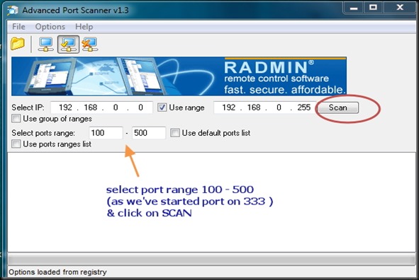
Open Port scanner & under Select port range enter 100 to 500 . As we’ve to check port 333 , we enter the range below 500 .Click on SCAN .

IP4


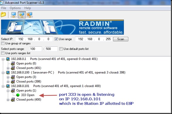
The PORT SCANNER displays the result regarding status of PORTs of your PC as well as the module connected to PC.

Here we can confirm that port 333 is OPEN on IP 192.168.0.101 (ESP module).

 ip5


STEP 4 : SET UP FORWARDING RULE on TPLINK CONFIGURATION

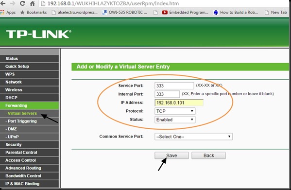
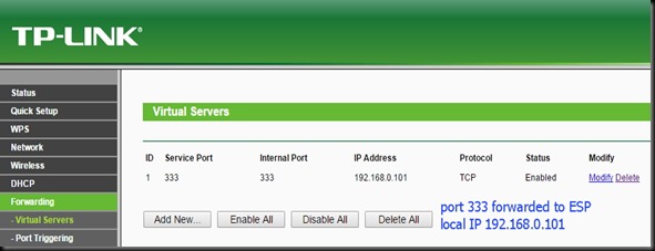
On TPLINK configuration window , under FORWARDING select the tab VIRTUAL SERVERS.

Click on ADD NEW.. & enter the Service & Internal port as 333 .

IP Address as 192.168.0.101 , which is the local IP allotted by Router to ESP module.

Select Protocol as TCP & then SAVE the settings.


IP9


IP 10


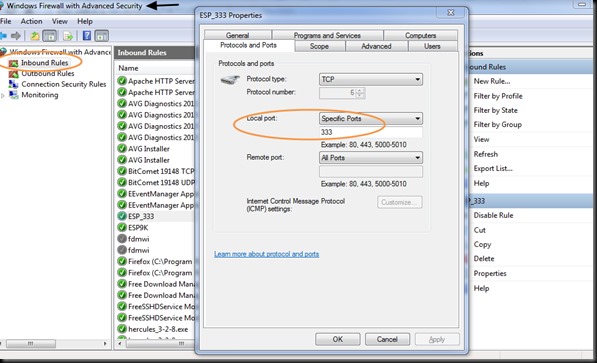
STEP 5 : WINDOWS FIREWALL SETTINGS

Open Windows Firewall Advanced settings & click on INBOUND RULES.

SET the rule to allow communication on port 333.

IP11


Now you are set to check the condition of PORT 333 externally.

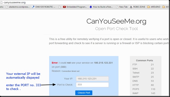
For this we make use of an online tool www.canyouseeme.org

On opening the site your external IP will be automatically displayed.Enter the port number to check.

Click on CHECK PORT.

ip 13

Unless you see SUCCESS on this test , you can’t contact your ESP module from external world.

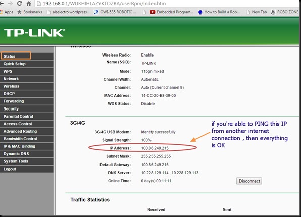
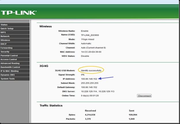
If you get ERROR , open the TPLINK configuration & click on STATUS.

Note IP Address displayed under 3G/4G.

From another computer with a different internet connection try to PING this IP address.

Open CMD & type in PING x.x.x.x

ip1


If the PING result is OK , you can be sure that the ESP module can be contacted from outside world.

If the PING result is TIMED OUT , you can’t communicate with ESP.

The   STATUS tab in my case , as shown in above screen shot , indicates an IP address starting 100.86.x.x

Generally following IP address ranges are PRIVATE IP ADDRESS RANGES :

10.x.x.x

172.16.x.x

192.168.x.x

These are reserved by IANA for private Intranets & NOT ROUTABLE TO INTERNET.

Private addresses are not reachable on the Internet. Therefore, Internet traffic from a host that has a private address must either send its requests to an Application layer gateway (such as a proxy server), which has a valid public address, or have its private address translated into a valid public address by a network address translator (NAT) before it is sent on the Internet.

In my case , the MTS ISP provider hide the PUBLIC IP address.

The MTS dongle does not support VIRTUAL SERVER settings , which means PORT FORWARDING IS NOT POSSIBLE with MTS.

What I couldn’t understand was , while writing my previous blog ,it worked sometimes.While MTS customer support was contacted repeatedly , they finally accepted that port forwarding is blocked by them.

After sleepless nights I’ve found a solution….. Read on my next post ….


cooltext753793315    cooltext753790696

Link to previous posts 1.AT Commands2. TCP Client/Server  , 3. Connect to Android


In the previous posts we’ve tested the WIFI module in TCP Server/Client mode & how to control from an Android mobile.These are related to LAN – Local Area Network where the WIFI module & Mobile are connected to the same ACCESS POINT (AP).

The AP  I’ve used is a WIFI Dongle MTS MBLAZE. For the outside world to contact the ESP module connected to MTS , PORT FORWARDING should be done. This is a method by which the IP address of ESP module is forwarded , so that any one accessing the particular port of external IP will land on the ESP module.

The problem is WIFI Dongles do not allow Port Forwarding  . As I’ve previous experience in CCTV  DVR port forwarding  (you can watch my video on DVR port forwarding Here )  using land line Internet connection , I decided to apply the same technique for ESP WIFI.

No Internet Dongle allows port forwarding. TPLINK MR3420 Wireless 3G/4G Router came to my rescue.

TL-3420-800x800

Following are the tasks we need to do :
1.Configure TPLINK ROUTER  to accept 3G Internet Dongle

2.Connect ESP to TPLINK on WIFI & Start a SERVER on port 333

3.PORT FORWARDING ESP’s IP on TPLINK ROUTER CONFIGURATION

4.WINDOWS FIREWALL SETTINGS

5 :Know your External IP & Port Open Condition

6.Connecting from a Distant PC anywhere in the World


STEP 1.CONFIGURE TPLINK TO ACCEPT 3G DONGLE

The TPLINK Router accepts USB Dongle as well as WAN connection.I plugged in my MTS dongle to the USB port of TPLINK.

One of the Ethernet ports is connected to the PC using RJ45 cable.

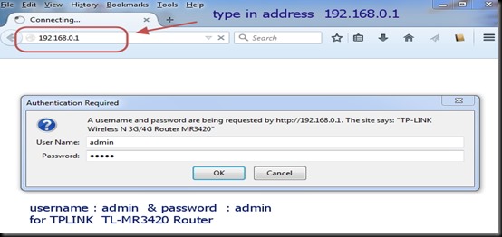
To configure the Router , open the browser & type in the Address of the Router .The IP address is 192.168.0.1

Both user name & password is admin

tp1

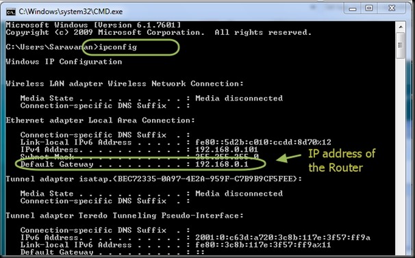
To know the Routers IP , you can type in CMD to open Command window .

After the prompt type the command “ipconfig” .The Default Gateway address is the IP of Router.

cmd1

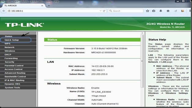
The configuration window of Router appears.

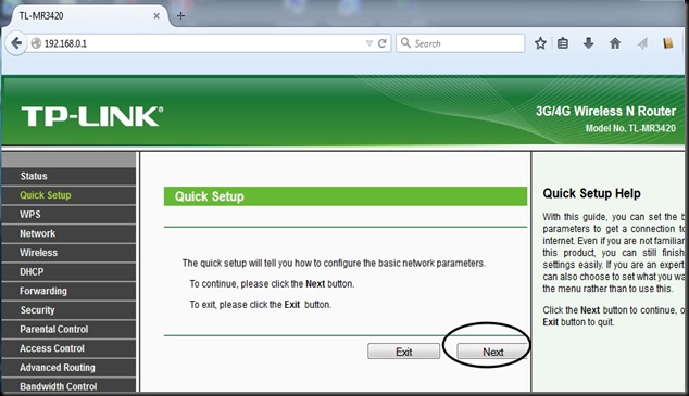
Select “QUICK SETUP”

tp2

Click Next button.

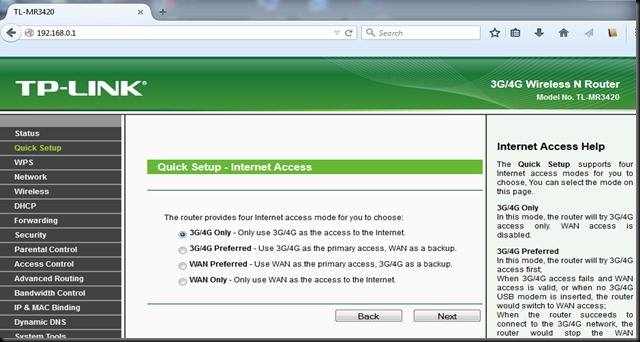
tp3

Select Internet access mode as “3G/4G ONLY”.

tp4

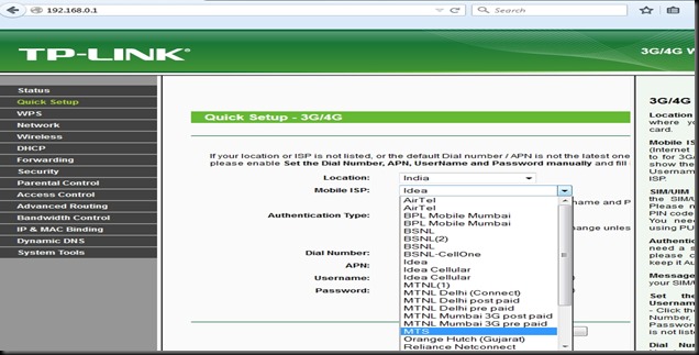
Select your Mobile ISP from the drop down menu .Mine is MTS .


tp5

Rest of the settings you can leave it for defaults.

tp6

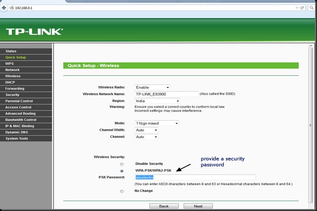
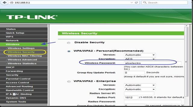
Click NEXT  & under Wireless Security select WPA2_PSK mode & provide a password.

tp7


tp13

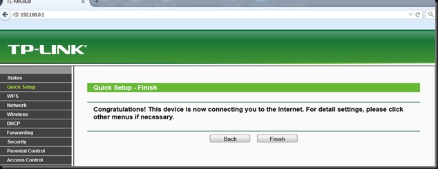
Click Next & then FINISH to complete the quick setup.

tp8


Under Status  you can see the 3G/4G USB Modem as Identified Successfully

tp11


For now the TPLINK Configuration is completed.We shall connect the ESP WIFI to TPLINK Access Point , Start a Server on ESP Module & again come back to TPLINK to configure PORT FORWARDING.


STEP 2 : Connect ESP to TPLINK on WIFI & Start a SERVER on port 333

We make use of Putty Terminal software to communicate with ESP module.

You can download PuTty here.

Open Putty & select Serial .Feed in the COM port where ESP is connected (through USB –TTL board) & select the Baud rate as 9600.

Now if you type in AT , you get OK response.

From the Putty window ,search for the surrounding Access Points (AP) using the command

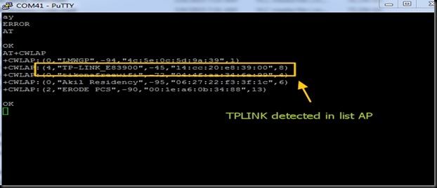
AT+CWLAP

You can see the TP-LINK under listed APs.

tp12


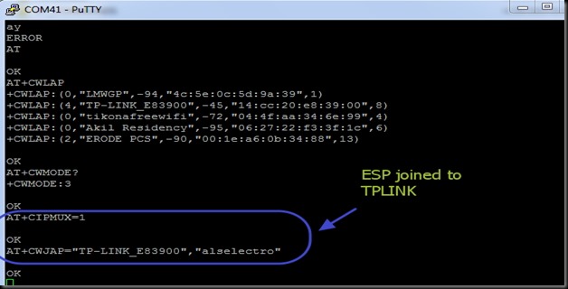
Join TPLINK AP using the password we’ve setup already with the Router.

AT+CWJAP=”TP-LINK_E83900”,”alselectro”

tp14

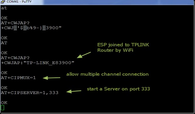
For allowing multiple connections

AT+CIPMUX=1

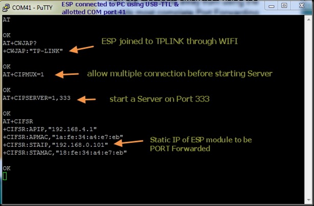
Now start a SERVER using command AT+CIPSERVER

You can use any port no. within 65536 , except the standard allotted ports like HTTP (port 80), FTP (21) , Telnet (23) , etc.,

The default server port for ESP is 333.Let us start a Server on that port using command :

AT+CIPSERVER=1,333


tpnew1

To know the Station IP  type in

AT+CIFSR

This returns the Access Point IP & the Station IP.

If CWMODE =1 , you get only the STAIP. Default is CWMODE=3 , which gives both IPs.

The STATION IP here is 192.168.0.100

tpnew2


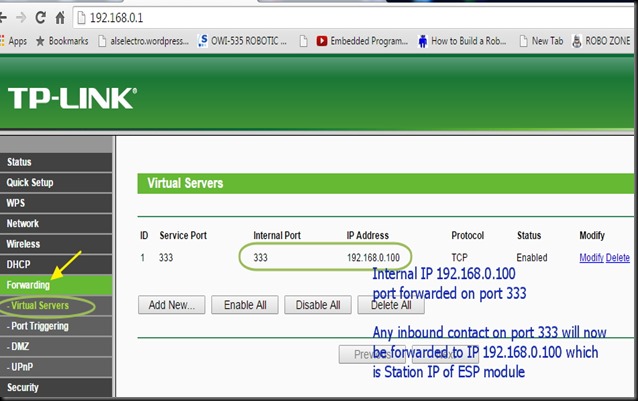
This Station IP is an Internal IP & cannot be contacted from outside world.To enable contact this IP , we need to PORT FORWARD .

As we’ve started a Server on port 333 , we shall forward any contact on this port to the Station IP.


STEP 3 : PORT FORWARDING ESP’s IP on TPLINK ROUTER CONFIGURATION
 

Open the TPLINK configure window which we’ve opened initially, by typing in 192.168.0.1 (IP of TPLINK Router ) , username & password both are –  admin

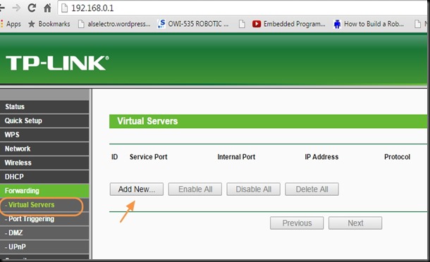
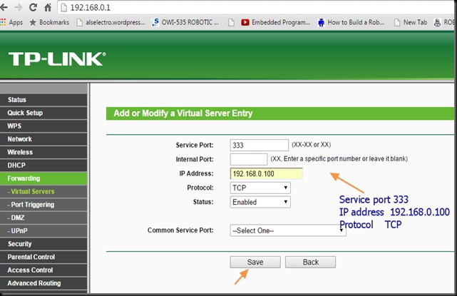
Under FORWARDING select VIRTUAL SERVERS

Click on ADD NEW..

tpnew9

Enter the Service port as 333 , as we’ve started a server on this port on ESP.

Fill in IP address as 192.168.0.100 , which is the Station IP of ESP.

Select Protocol as TCP & Status Enabled.

Click on SAVE . The Internal port will be assigned same as Service port automatically.

tpnew10


tpnew3


Now we need to allow this port for incoming traffic on the Windows Firewall settings.


STEP 4: WINDOWS FIREWALL SETTINGS :
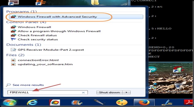
Type in FIREWALL on Windows search bar & select “Windows Firewall with Advanced Security “


tp27

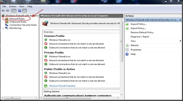
Select “INBOUND RULES “ on the left pane.


tp28

Click on “NEW RULES” on the right Actions pane


tp29

Select PORT as Rule type on the next screen.

tp30

Select Protocol as TCP & enter the port number 333  under Specific Local Ports.


tp31

Select “Allow the Connection “.

tp32

Apply rule to all  Domain,Private & Public.

tp33

You can name the rule & click Finish to save it.

tp34

STEP 5 :Know your External IP & Port Open Condition

The Router is accessed from outside world by its external IP. This external IP is assigned by the ISP provider.Generally this IP is DYNAMIC ,which means every time you switch on your Router , a different IP is assigned.

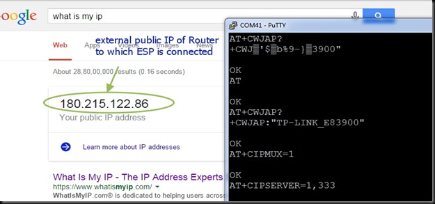
For a fixed IP , you’ve to contact your ISP provider & pay for a STATIC IP.

Open your web browser & Google for “ what is my ip “

Your public IP address will  be displayed.Note that down.

tpnew4

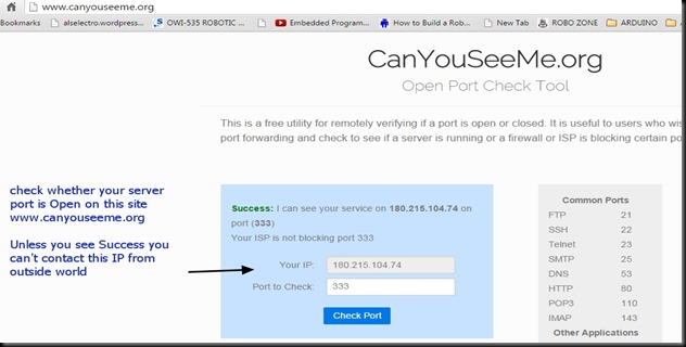
Now we shall check whether the port 333 is open or not.

Visit the site  www.canyouseeme.org

Your IP will be automatically displayed.Under  “ Port to Check “ enter the port number 333

& click on CHECK PORT.

You see SUCCESS message only on following conditions :

1. Router TPLINK Port Forwarding setting is done so that incoming request on port 333 is forwarded to the Station IP of ESP.

2. Windows Firewall setting Inbound Rule is set to allow communication on port 333.


tpnew5


Only on getting  SUCCESS message under Canyouseeme.org you can proceed further.

Till now all settings & configurations are done on PC connected with TPLINK & ESP.

Next is the final step in which another PC is involved from anywhere in the world.


FINAL STEP 6 : Connecting from a Distant PC anywhere in the World


For demo purpose I’m using a separate PC with a different Internet connection.

You can see from screen shot below the IP address of the distant PC.

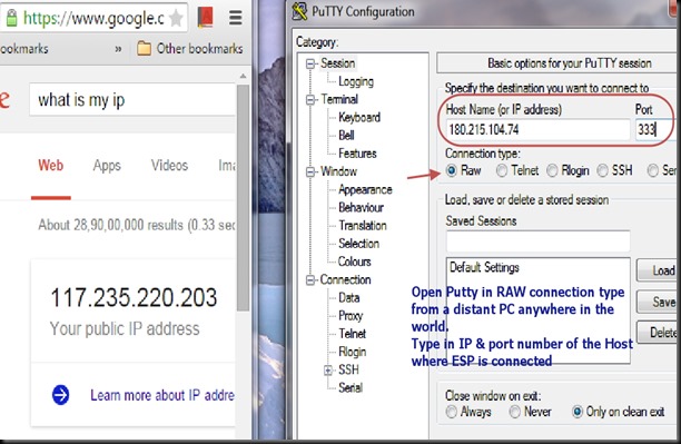
Open Putty window in that PC & select RAW as Connection type.

Feed in the External IP address to be contacted (that of ESP ) & enter the Port no. as 333

TPW3

After entering the details , click on Load button.

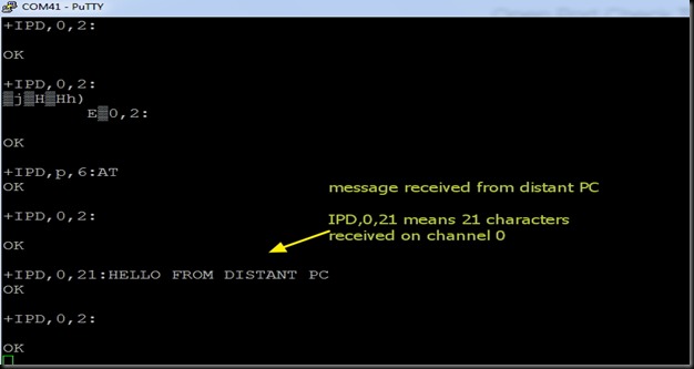
Immediately you get response on the Putty window of ESP , like ,  +IPD,0,2:

From distant PC Putty window type in some characters .This will be received in the ESP window.


tpnew6

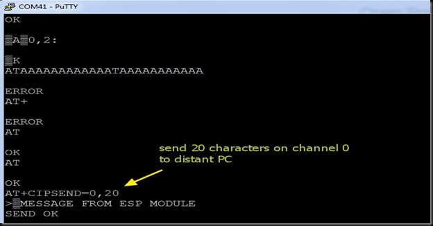
To send data from ESP , use command :

AT+CIPSEND=0,20

This command waits for you to type 20 characters to be sent on channel 0.

tpnew7

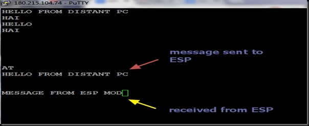
The following is the screen shot of Distant PC Putty window.

Note the IP address of distant PC on top of putty window.

TPW5


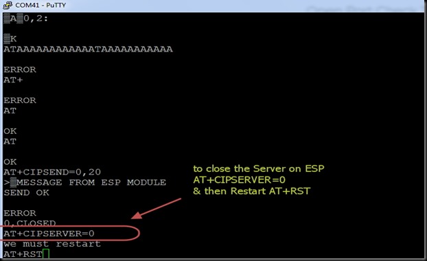
To close the Server on the ESP side , use command :

AT+CIPSERVER=0

& then Restart using AT+RST


tpnew8


Once you know the external public IP address of the Router & the Port number on which the server is started, you can contact this ESP from anywhere in the world !!!!


cooltext753793315     cooltext753790696