Category: 8051


Image 1Image 2

89s52  is widely used  IC in 8051 FAMILY.

It is programmed using ICSP with an external programmer USBASP (AVRDUDE).

89S52 has no BOOTLOADER , so it cannot be programmed through SERIAL Port.

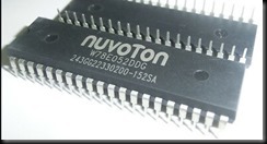
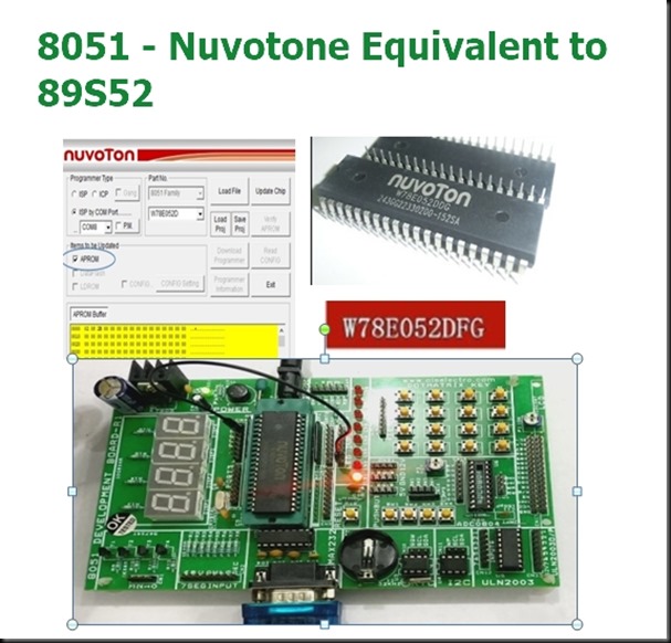
W78E052DDG is 8051 compatible 8-bit controller from Nuvoton with 8K programmable flash memory in 40 Pin DIP package

This chip has separate dedicated 2K boot-loader memory, which makes this chip robust and very stable .It supports ISP program downloading from PC using RX-TX lines only.

Other specifications match exactly 89S52.

It contains an 8K-byte Flash EPROM , a 256-byte RAM; four 8-bit bi-directional (P0, P1, P2, P3) and bit-addressable I/O ports , an additional 4-bit I/O port P4; three 16-bit timer/counters ,  a hardware watchdog timer , and a serial port

The instruction set is fully compatible with the standard 8052. Note that the actual part number of the chip in the 40-pin DIP package is W78E052DDG

TITLE

Because the Nuvoton W78E052D microcontroller comes with a UART boot-loader, it can directly be programmed from the serial (COM) port. You can use “Nuvoton ISP-ICP Utility software” to program the target MCU with the help of a  USB TO RS232 Cable

This cable has CH340 serial IC inside.

Driver for CH340 to be installed in PC , for COM port allotment.

Image 1

The same development of 89S52 can be used for Nuvotone  IC.

Image 2


Note that in this procedure, the MCU’s Reset (RST) pin is controlled by the programmer; hence, a power cycling should become necessary in most situations.

The microcontroller needs an oscillator for its clock generation, so an external 11.0592-MHz crystal with two 22-pF capacitors as shown in the hardware setup diagram is required.

Furthermore, the chip has no internal power-on-reset, so it is achieved externally through the Reset pin using a 10-uF capacitor or 0.1 uf and a 10K resistor.

Image 19

Details of programming from the official Nuvotone site :

For the 8051 MCU products with ISP function, there are two program memories: one is APROM and the other is LDROM. APROM contains the user’s application code for normal operation while LDROM contains the ISP code (cooperating with the ISP Programmer) for updating of APROM.

To use the ISP Programmer to update APROM, the ISP code should always reside in LDROM. If the ISP code disappears from LDROM because of accidentally being erased by a universal programmer, the ISP function will become always failed.

To recover the ISP function, please use a universal programmer to program the Nuvoton standard ISP code into LDROM, and have its CONFIG setting properly configured .

Why is the ISP code easily/accidentally erased by a universal programmer? Because the LDROM is also erased along with the APROM if the user uses a universal programmer to program APROM.

So, it is  strongly recommended  to use the ISP Programmer to program APROM in the beginning of getting the MCU sample with ISP code inside. Don’t use any universal programmer to program APROM unless the ISP function won’t be used.

The difference between ISP (In-System Programming) and ICP (In-Circuit Programming) is that ISP is implemented by software control of MCU itself while ICP is implemented by hardware control. So, before updating the MCU chip, ISP needs a software code (the ISP-code) pre-programmed in MCU’s LDROM to function as software control while ICP doesn’t need any software code pre-programmed.

During ISP operation, the 8051 MCU’s P3.1 behaves as ‘DTA’ (serial data). When ISP is not requested, P3.1 can function as its normal general purpose I/O pin as long as P3.1 conforms to the following requirements: * The state of P3.1 must be logic-1 before the MCU is just released from reset condition. * During the ISP operation, P3.1 cannot be pulled low by the other components connected to it.

Nuvotone Utility IDE is used to dump HEX file on to the Nuvotone Chip.

Download the utility here :

http://www.alselectro.com/files/8051_nuvotone.zip


Image 3

Open the Utility

Select ISP BY COM PORT & SELECT THE COM PORT from the drop down menu.

Part no as W78E052D , items to be updated APROM.

Click on LOAD FILE button and browse to the location of the HEX file to load on the APROM Buffer.


Image 3


The creation of HEX file is similar to that of 89S52 using KEIL U-VISION software.

Open KEIL & create NEW Project.

Select Device for target as W79E052D ( selection of 89S52 also works).

Image 1


Image 2

Right click Target & under options for Target click on OUTPUT tab & put a tick mark against

CREATE HEX File.

Image 3


Right click SOURCE GROUP & click Add New item to Group.

Select C File & provide a name for the file.

Image 4


Now write your C code & click on BUILD or press F7 key.


Image 5


Image 6

Your HEX file is created under Objects folder.

Image 7


Image 8

Click on LOAD FILE in the NUVOTONE Utility & browse to the HEX file location to select it.

Image 9


Ensure that APROM is selected in the utility.

Image 10


Now click on UPDATE CHIP.

While you see the blue update bar at the bottom you must press the RESET button on the development board.

Image 11


If RESET button is not pressed , you get FAIL report.

Also note that the NUVOTONE Utility must be started in ADMIN mode.


Image 12


Image 14

Once you get the PASS report , you need to press the OK button.

This will execute the file loaded.

Image 15

There is also a P.M selection for multiple IC programming.

Tick mark this P.M & click on UPDATE CHIP.

You can program multiple chips in this mode ,

After RESET you can change the IC & program repeatedly.


Image 13


VIDEO :


blog_image

USBASP programmer is widely used to upload  .HEX file on to AVR / 8051 ICs.

On Windows 10 PC you may face some driver installation problems.Check out my previous blog on how to install drivers.

https://alselectro.wordpress.com/2018/06/08/usbasp-how-to-install-driver-on-windows-8-10/

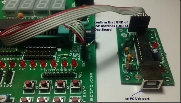
While connecting USBASP to 8051 development board , take care that GND pin matches GND of both boards.

No separate power source required for development board.It can source from USB itself.


IMG_20190328_165320

Connect USBASP to PC .

Install driver from link below:

USBASP Driver :

https://protostack.com.au/download/USBasp-win-driver-x86-x64-v3.0.7.zip

Once driver is installed , under Device Manager USBASP appears.


Image 1


PROG ISP software IDE is used to upload HEX file on to 8051 IC.

Download link is below

PROG ISP :

http://exploreembedded.com/wiki/images/1/1a/Progisp1.72.rar

No installation is required.Unzip the downloaded file and double click on PROGISP application.

On top you can see two blocks ,  PRG ISP &  USBASP

PRG ISP will be greyed out if programmer is not found on not connected.

USB ASP will be greyed out if driver is not installed.

Ensure that these two blocks are not greyed out.


Image 2

Select your IC from drop down menu. 89C52 or 89S52   , select the correct part no.

Click on Erase button.

If the usbasp device is ok , the erase will be performed.

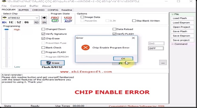
Here Im getting the infamous CHIP ENABLE Error.


Image 3

This error persists even after , Programming power  adjusted using slider & Verify Signature tick mark  removed .

CHIP ENABLE error occurs if the IC is not placed correctly on ZIF socket of development board or if the wrong Chip  is selected.

If still the problem persists , then you need to upgrade FIRMWARE of USBASP.

For this we use ARDUINO UNO in ISP mode.


IMG_20190328_170032


Connect UNO to PC & note the COM port allotted.

Open Arduino IDE .

From Tools select the board as Arduino UNO, Port as COM port allotted

Programmer is selected as ARDUINO AS ISP.


Image 4

Under File  –> Examples  –>  select  ARDUINOISP

Upload the sketch. Now Arduino is ready as ISP programmer.


Image 5


Now download the USBASP Firmware from the developers website

usbasp Firmware

https://www.fischl.de/usbasp/

Image 6

Download the .tar.gz file & unzip twice. Under bin –> firmare you can see the Atmega8 firmware file in .hex format.

Note the path where this file is saved.

To upload firmware we use AVRDUDES GUI application

Download it from link below and install it.

AVR DUDES :
http://blog.zakkemble.net/avrdudess-a-gui-for-avrdude/


Connect Arduino with USBASP as follows :
ARDUINO     USBASP

5V        —>  Vcc

Gnd      —>  Gnd

10         —> RST

11      —>  MOSI

12       –>  MISO

13       —>  SCK


Connect USB of PC to ARDUINO  ( not to usbasp)

Arduino is Master and USBASP is slave

IMG_20190328_171442

Open AVRDUDES

Select Programmer as ARDUINO

COM port as port allotted to Arduino

Baud rate 19200  ,if you try any other baud it shows time out error.

Bit clock –leave it blank

Target MCU select as ATMEGA8

Under FLASH click on …  and browse to select the firmware file  we downloaded earlier.

Fuses can be set as  Low Fuse  : 0xFF  , High Fuse : 0xE9,  select tick mark against SET FUSES.


Image 7

Now click on DETECT

I get an error saying signature 00000 , which means target is not detected.


Image 8


If you check the schematic of USBASP , a jumper JP2 is to be ON to enable self programming.

This jumper is between pins 1 & 16 (slave select pin) of USBASP IC.

u1

As my USBASP is not having this jumper I soldered a 270E resistor between pins 1  &  16.


IMG_20190328_172731


IMG_20190328_172955


Now I tried DETECT on AVRDUDES.

Target is detected & the signature of ATMEGA8 is 1E9307.


Image 10

Now on clicking PROGRAM button , the firmware is flashed successfully.

I just removed the resistor and tried uploading hex on to 8051 successfully.


Let us see the second method of upgrading firmware .

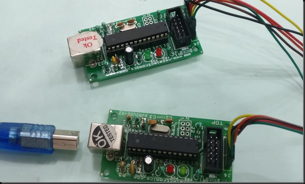
Here we use another working USBASP programmer instead of ARDUINO.

Connection is one to one

Vcc to vcc , Gnd to Gnd , MOSI toMOSI , MISO to MISO , RST to RST


IMG_20190328_182945

On target USBASP a 270 E resistor soldered between pins 1 & 16.


IMG_20190328_183000

PC is connected to  Master USBASP.

Open AVRDUDES.

Select programmer as USBASP , port as USB , Baud as 19200

Bit clock will be automatically selected as 1.5MHz


Image 12

Click on Program to see the firmware upgraded successfully.

This method is slower than Arduino method.

Ignore any SCK clock error which occurs due to un success full bit clock setting.

Image 13


VIDEO SUPPORT :


blog_image


Installing USBASP drivers on Windows 8 or 10 is bit tricky. As these versions of Windows require DEVICE DRIVER VERIFICATION , they do not allow unsigned drivers like libusb.

For programming 8051 or AVR you need this driver.

You can install by following methods :

1. Disabling Windows driver enforcement on boot up. Follow this link

https://alselectro.wordpress.com/2013/11/02/usbasp-drivers-not-installing-on-win-8-pc/

This method requires SHIFT+ RESTART of Windows to enter advanced troubleshooting where we disable signature verification .After this you can install the libusb driver.

But in some laptops , this method fails on next Windows update.


2. Install libusb drivers using ZADIG application.

http://zadig.akeo.ie/

Zadig is meant to install a libusb compatible driver, for a device that does not yet have such a driver installed.

With the application running, you should see your USB device appear in the dropdown list

(click on the dropdown to see all devices).
You can also plug your USB device after Zadig is running, as the list is refreshed automatically. Its recommended to leave only the device you want to install a driver for, and unplug any other USB device.


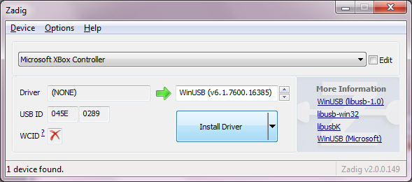
You can also select the driver you want to install,( between WinUSB/ libusb-win32/libusb0 / libusbK )

Once you are satisfied with the selection and device description, simply click the Install Driver Button.

Caution :

If you select the wrong device,  Zadig will  replace its driver.

The responsibility is entirely yours try to pay attention to the device you select .Don’t just  press the install button on the first device you see,

If wrong driver is replaced , then some of your USB devices like wireless mouse may not work.


3. Best & Easy method

The USBASP windows driver was previously based on  libusb-win32. The certificate on the base drivers have expired and the library has now been superseded by libusbK.


Following is the procedure to install protostack USBASP driver.

At first when you connect the USBASP hardware to PC & open the Device Manager you see an exclamation mark against USBASP indicating that drivers not installed.


Image 2

If you open the PROGISP application ( to load HEX file on to8051) ,you see the PRG ISP icon greyed out ,as the programmer is not yet detected.

Image 1


Download the new USBASP driver from

https://protostack.com.au/download/USBasp-win-driver-x86-x64-v3.0.7.zip

This driver should work with version of Windows XP right through to 8.1 and the version 10 . (both 32 and 64 bit editions).

Because the driver is signed, there should be no need to disable driver certificate enforcement or use Zadig.

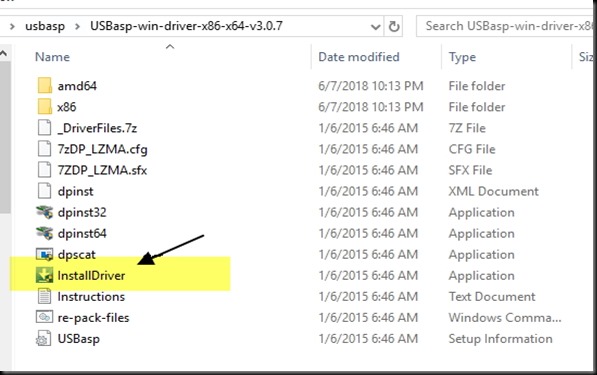
Unzip the downloaded folder.

Click on Install Driver application

Image 4


Image 5


Image 6

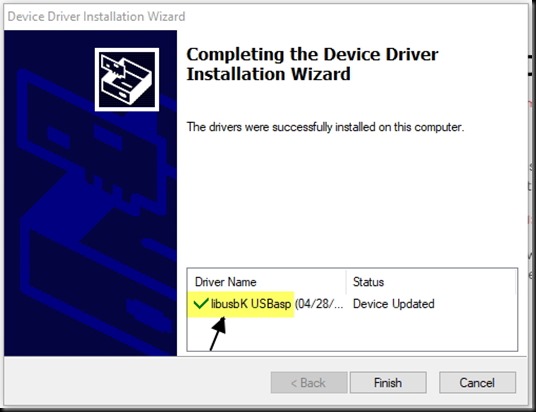
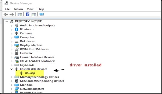
Once the driver is installed , under Device Manager you can see USABASP under

libusbK Usb devices

Image 7

Now ,open the PROGISP application to see the device ready.

Image 8

blog_image

The popular 16 x 2 LCD can be interfaced with 89S52 in 4 bit or 8 bit mode. To save port pins of microcontroller , often the LCD is used in 4 bit mode.

The connection details are :

Data pins  D4  — P2.0  (pin 21)

                  D5  — P2.1 (pin22)

                  D6  — P2.2 (pin23)

                  D7  — P2.3 (pin24)

Control pins  RS  — P0.0 (pin 39)

                      EN  — P0.1 (pin 38)

                      R/W – GND  


89s51_lcd


A header file defining all Functions related to LCD control is created and available for Download here .

Including this header file into your project makes programming much easier.

To start with create a folder  for your project , say F:\LCD

Open the KEIL IDE

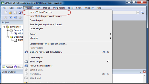
Click Project – > New uVision Project & browse to the location of the folder created F:\LCD

Provide a filename for the project & select the Target as AT89S52.

Click OK to get the Target1 on the project pane.

Right click the Target1 & click on “Options for Target Target1”

Image 2


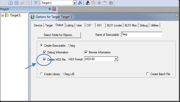
On the Options windows , select the OUTPUT tab & then check mark the box which says “Create HEX file”

Image 3

Now copy the downloaded lcd.h Header file & paste it to the project folder .

Image 5


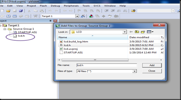
Back to KEIL IDE , Right click on “Source Group 1” & click on “Add Existing Files to Group “

Browse to the lcd.h file you’ve added to the project & select it.

Image 4


Now the Header file is included in to the project folder.


Image 6

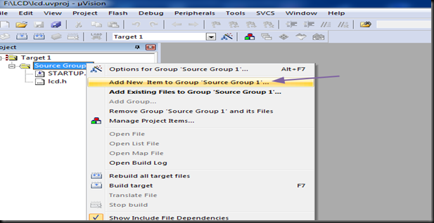
Right click again on the Source Group 1 & click on “Add new item to Group “

Image 7

On the next screen select the first option “C File “ & provide a name to your C file.


Image 9

Feed in the following code :

—————————————-

#include<reg52.h> //including sfr registers for ports of 89s52
#include<lcd.h>  // lcd header file

//LCD Module Connections
sbit RS = P0^0;
sbit EN = P0^1;
sbit D4 = P2^0;
sbit D5 = P2^1;
sbit D6 = P2^2;
sbit D7 = P2^3;
//End LCD Module Connections
void Delay(int a)
{
  int j;
  int i;
  for(i=0;i<a;i++)
  {
    for(j=0;j<100;j++)
    {
    }
  }
   
}
void main()
{
  int i;
  Lcd_Init();
    Lcd_Clear();
  while(1)
  {
    Lcd_Set_Cursor(1,1);
    Lcd_Write_String("8051 LCD Interface");
    for(i=0;i<18;i++)
    {
      Delay(1000);
      Lcd_Shift_Left();
    }
    for(i=0;i<18;i++)
    {
      Delay(1000);
      Lcd_Shift_Right();
    }
    Lcd_Clear();
    Lcd_Set_Cursor(2,1);
    Lcd_Write_Char(‘S’);
    Lcd_Write_Char(‘E’);
    Delay(2000);
  }
}

————————————————

After feeding in the code , click the Save button.

Now click F7 or the Build button to start building target.


Image 10

If the code syntax are correct , you get “Creating HEX file “ display on the Output window.


Image 13

Now the HEX file is successfully created inside your project folder.

Image 11


Connect the ISP programmer to the Development board.Plug in the LCD module on to the LCD port connector.

Connect the USB cable to PC & open the PROGISP software.

Click on File & “Load Flash “ .Browse to the location of the HEX file & select it.

Click on AUTO to perform the programming.


Image 12

Now you can see the characters displayed on the LCD.You can adjust the small blue preset if nothing is seen on the LCD.

lcd1 (1)

LCD HEADER file & C file DOWNLOAD

There are 2 types of 7 segment displays , Common Anode & Common Cathode.In this post we shall see how to interface a Common Cathode display with 89S52 Microcontroller.

As the name indicates the cathode points of all segments are made common to GND .To make a segment Glow , the corresponding segment pin is made HIGH.


                Image 3

The PORT pins P2.0 to P2.6  are  connected to segments a through  g. The dot pin can be left out.

A NPN transistor is used at the common cathode point . When the base of transistor is made HIGH , it conducts & applies Ground to the Common Cathode point.The transistor is controlled by port pin P1.0

Image 1


Following table explains how to arrive at the HEX value for displaying each Digit.

For e.g , to display digit 1 , the segments b & c should be High & all others Low.This corresponds to 0x06 in Hex format.

Similarly to display digit 0 , all segments , except g should be made High, which is hex 0x3F.

For this demo , we do not use the Dot .Hence it is 0 for calculating all other digits.


Image 2


To start with create a folder say , F:\7segment  to store project files.

Open KEIL click on Project –> New uVision Project & browse to the location of the folder created.Provide a filename & Save.

Select the Target Device as ATMEL AT89S52.

Target1 is created in Project file window of KEIL.

Right click Target 1 & click on “Options for Target Target1”

Image 4

On the Options Window select the tab “ OUTPUT”

Check mark the box “Create HEX file” . This step is important & if you forget check marking this box , no HEX file will be generated.


Image 5


Now to add the C file to project , Right click Source Group 1 & click on “Add new item to Group “l

Image 6


Select the first option C File & provide a Name .Click on ADD

Image 8


You can see the .C file added to the project .

Image9

Type in the following  code :

—————————————————————

// Port pin P1.0 is used to Enable the 7 segment CC display
//Port pins of P2 are connected to each segment of CC display

#include<reg52.h>
sbit ledenable=P1^0;
void delay(void);

void main()
{
    P2 = 0x00;
    ledenable=0;
while(1)                  //indefinite loop
  {
     ledenable=1;           // Enable pin for Common cathode display
   P2=0x3f;                          //Display digit 0
   delay();
   P2=0x06;                          //Display digit 1
   delay();
   P2=0x5b;                          //Display digit 2
   delay();
   P2=0x4f;                          //Display digit 3
   delay();
   P2=0x66;                          //Display digit 4
   delay();
   P2=0x6d;                          //Display digit 5
   delay();
   P2=0x7c;                          //Display digit 6
   delay();
   P2=0x07;                          //Display digit 7
   delay();
   P2=0x7f;                          //Display digit 8
   delay();
   P2=0x6f;                          //Display digit 9
   delay();
  }
}
void delay(void)
{
    int j;
    int i;
    for(i=0;i<10;i++)
    {
        for(j=0;j<10000;j++)
        {
        }
    }
}

—————————————–

Instead of a long code you can also use Array as below

First initialize all the segment hex values of the digits in an array.


unsigned char digit[10]={0x3f,0x06,0x5b,0x4f,0x66,0x6d,0x7d,0x07,0x7f,0x67};

Now take for loop and assign array values to the PORT2 with some time delay.

Here is the code using Array :

——————————————————-

#include<reg52.h>

sbit ledenable=P1^0;
void delay();
unsigned char digit[]={0x3f,0x06,0x5b,0x4f,0x66,0x6d,0x7d,0x07,0x7f,0x67};
unsigned int k;
void main()
{
    P2 = 0x00;
    ledenable=0;
   
  while(1)                  //indefinite loop
   {
    ledenable=1;         // Enable pin for Common cathode display
    
       for(k=0;k<10;k++)
        {
           P2=digit[k];
           delay();
        }
   }
}

void delay()
{
    int j;
    int i;
    for(i=0;i<10;i++)
    {
        for(j=0;j<10000;j++)
        {
        }
    }
}

———————————————————–


After Feeding in the code click on SAVE button & then F7 to build the project.


Image10


If all syntax are correct , compiling will be successful.


Image 11

Inside the Project folder you can see the HEX file created.This is the file we’re going to fuse on the Target chip.

Image13


Connect the ISP board to the Development board & finally connect the USB cable to pc.

Open the PROGISP software .The PRG ISP & USB ASP buttons should be activated.If any one is greyed out then check for the drivers to be installed for the ISP board.

Click on FILE –> LOAD FLASH & browse to the location of the project folder where the HEX file was generated.

Select the HEX file  .Click on AUTO button to perform the programming.

image12

Once the HEX file is fused , you can see the result on the 7 segment display counting from 0 to 9.


7SEG21

The main & first part of your embedded project is creation of .HEX file from the C or Assembly code.For 8051 devices KEIL MICROVISION is a well known IDE .

The free version of KEIL has a limitation of 2k code size.  Programs that generate more than 2 Kbytes of object code will not compile, assemble, or link in the free version.

This software is an integrated development environment (IDE), which integrates a text editor to write programs & a compiler which converts your source code to hex file.This HEX file is then fused on to the target chip.

The free version can be downloaded from :

https://www.keil.com/demo/eval/c51.htm

Install the downloaded KEIL software & open it.

The IDE is simple with 3 windows : Project Workspace , Editing Window & the Output window

Image 2


Before starting with your new  project , create a folder for your project. For this e.g we create a folder F:\blinkled

Click on Project – > New uvision project  & browse to the location of the folder we created in F:\

Image 3


Provide a filename as “blinkled” & click on Save.

Image 4


Device selection window opens automatically. Select the target device as AT89S52 & click OK.

Image 6


Confirm with YES button on the next screen.

Image 7

You can see the TARGET1 created under the Project space.


Image 8

Right Click on that Target1 & select Options for Target

Image 22

A new Options window opens.Click on the OUTPUT tab .Tick mark against “Create Hex File “.

If you forget to check this option , you will not find the HEX file in the project folder after a Build.


Image 10


Click OK to close the Options window.

To add the .C file Right click on Source Group1 under Target1 & click on “ Add New item to Group”

Image 11


On the next screen select the first option C File ,provide a name & click on ADD.


Image 12


Now your .c file is added to the Source Group.

Image 13


Enter the following code in to the Editor window.

This sample code makes the LED connected to port pin P1.0 BLINK .


————————————–

// Program to blink an LED at Port pin P1.0 (physical pin 1 of IC)

#include<reg52.h>  // special function register declarations for 89s52                

#include<stdio.h>  // prototype declarations for I/O functions

sbit LED = P1^0;    // defining pin P1^0 as LED

void delay(void) ;  //delay function prototype declaration

void main (void)
   
{
    LED = 0 ;              // Make LED pin as Output
    while(1)                //indefinite loop
    {
       LED = 0;           // LED Off
       delay();
       LED = 1;          // LED ON 
       delay();
    }
}

void delay(void)
{
    int j;
    int i;
    for(i=0;i<10;i++)
    {
        for(j=0;j<10000;j++)
        {
        }
    }
}

—————————————————–

After entering the code click on the SAVE icon .Now the * mark will vanish on the main.c file.

Image 19


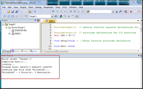
Press F7 or click on the BUILD  button to start compiling the code.

Image 20

If there is no syntax error , a HEX file is created inside your project folder.

Image 21

This .HEX file has to be fused on to the Target chip using the ISP programmer & PROGISP software.

This Fusing procedure is explained in the next post.


SIMULATION :

KEIL’s inbuilt Debug can be used for Simulation of the code , without any physical Hardware.

Click on Debug – > Start/stop Debug session.


Image 23

Now your project workspace window shows most of the SFRs as well as GPRs r0-r7. Also one more window “Watches “ is now open. In this window you can see different variable values.

To add variable in watch window goto "watch#1" tab. Type F2 to edit and enter the name of your variable .

To see the output on ports ,under Peripherals—> select I/O ports – > Port 1.

You can give input to port pins by checking or unchecking the check box. here the check mark means digit 1 and no check mark means 0. The output on the pin will be shown in same manner

To run the program you can use any of the option provided "go", "step by step", "step forward", "step ove" etc.


Image 24


Press F5 to start simulation .The port pin 1.0 starts blinking to show the result.

Image 25

Click on Debug – > Stop to Exit simulation.

Image 26


The 8051 development board can be used as a learners kit as well as a project board.

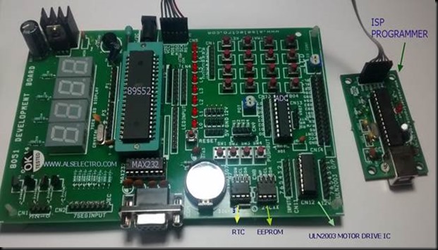
An ISP programmer is required to fuse the HEX file on to the target 40 pin IC (89S 51 or 89S 52).

The HEX file is created using KEIL software. See previous post to create HEX file

clip_image002

Care should be taken while connecting the ISP programmer with the Development board.Look out for the GND connection printed on the boards .

The GND of ISP must match the GND of Development board.

Connect the USB cable of ISP programmer to USB port of your PC.

No external power is required for the Development board.Power is sourced from USB port of PC.

clip_image004

PROGISP is the software used to load the HEX file on to the target chip.

KEIL Microvision is the software to create HEX file using C code or Assembly language.

Download the software here :

http://www.alselectro.com/files/8051_isp.zip

The drivers for the ISP Programmer is found inside the Drivers folder of PROGISP.

clip_image005

Open the DEVICE Manager of your PC while connecting the ISP programmer to USB port.If you get an exclamation mark against device , Update driver & browse to the location of Drivers inside PROGISP folder you’ve downloaded.

Once the Drivers are installed you get the USBasp under Device manager.

The setup is now ready to load the HEX file.

clip_image006

We use the PROGISP application to load the HEX file on to the target IC. No installation is required for this software , it’s a standalone one.

Double click progisp.exe to open the application.

The PRG ISP & USB ASP buttons should be bright .If it’s greyed out , then check the USB cable connection & the driver installation.

clip_image008

Select the target chip (here 89S 52) from the “Select Chip “ drop down menu.

Ensure that following buttons are Enabled :

Verify Signature

Chip Erase

Program Flash

Verify Flash

If you enable the LOCK CHIP button , others can’t make a copy of your chip.

clip_image010

Click on FILE — > LOAD FLASH & browse to the location of the HEX file you’ve created using KEIL.

clip_image012

clip_image014

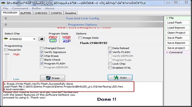
Once the HEX file is loaded , click on AUTO button to perform the tasks you’ve enabled.

clip_image016

The status bar at the bottom indicates the progress of operation.

clip_image018

clip_image020

Finally the HEX is successfully loaded on to the target chip.

clip_image022

If the PROGRAM FLASH button is not enabled , you get Flash Verify Error while fusing.

clip_image023 clip_image025

alselectro@gmail.com Technical Blog : http://www.alselectro.wordpress.com


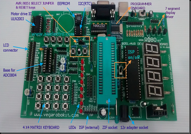
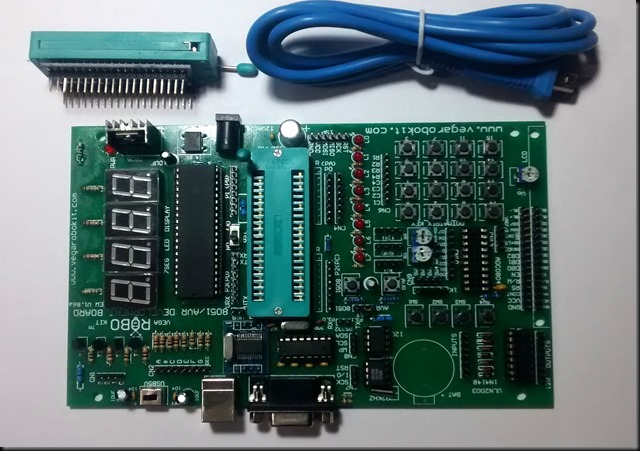
First time in India , VEGA ROBOKITS has engineered a development board universal to both AVR & 8051 ICs.The board has in built Programmer capable of programming both AVR & 8051 family ICs.


board2


A 40 pin ZIF socket is used as Target to hold the 8051 IC. Additional 40 pin ZIF socket with modified connection is provided to host AVR ICs.This additional ZIF socket should be placed over the on- board ZIF socket to use AVR ICs.


image4


board1


8051 PROGRAMMER & DEVELOPMENT

To start with we shall see how to use this board for 8051 development.

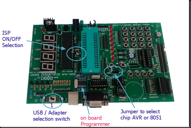
Select switch 1 to USB position ,if you connect the board to PC using A to B USB cable.Now the power is taken from USB itself. If this switch is selected to other side , the board needs an external 12v/1A adapter.

Select the ISP switch (switch 2 near the middle of board) to ON position.This makes sure that you’re going to program the chip .

Put the jumper (found on top of I2C EEPROM IC) on 8051 position.


WILPRO’s WLAR software is used as an application to fuse the HEX files.Download the zip file from :

http://www.alselectro.com/files/wlpro_v220_setup.rar

No installation is required.It is a standalone application.

Download the drivers required for this board from :

http://www.prolific.com.tw/UserFiles/files/PL2303_Prolific_DriverInstaller_v1_10_0_20140925.zip

Unzip the driver file & double click on  “PL2303_Prolific_DriverInstaller_v1.10.0 “  EXE file to install the drivers.

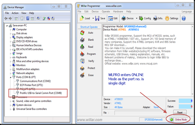
Connect the USB cable of board to PC & open the DEVICE MANAGER.

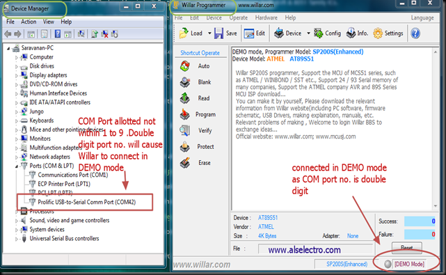
If the PORT allotted is within range 1 to 9 , you can start the WLPRO application and proceed to load HEX file.

If the port allotted is a double digit , then WLPRO will enter DEMO mode .Only in ON LINE Mode you can load the HEX file.


g1


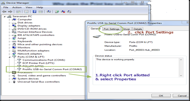
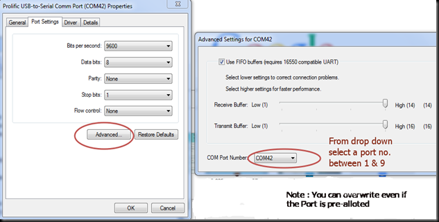
To solve this , RIGHT CLICK on the port allotted inside Device Manager & select PROPERTIES.

Under PROPERTIES window select PORT SETTINGS


g2

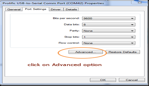
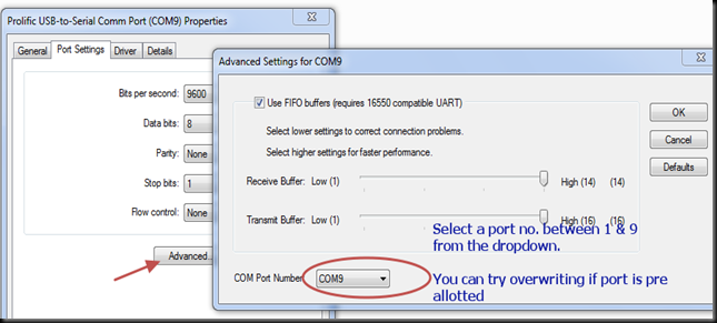
Click on ADVANCED button under PORT SETTINGS.


     g3

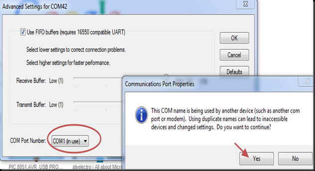
From the DROP DOWN you can select a PORT number between 1 & 9  &  click OK.

If the port number is not free , you can try overwriting the pre allotted port number & confirm.


g4


g6


g5


After PORT setting to single digit  , open the WILLAR software . Now you can see ONLINE MODE at the bottom of screen.


g7

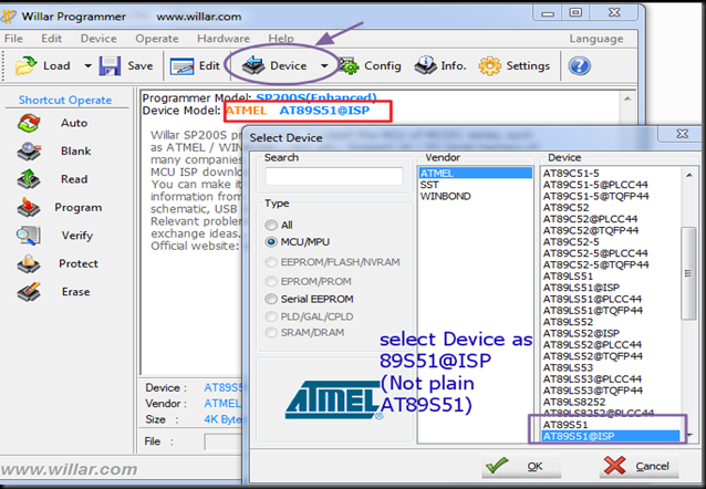
Click on DEVICE button & select the target device as AT89S51@ISP 

If you select plain AT89S51 , DEVICE ID ERROR will be returned while programming .So make sure to select the ISP version as device.

Image 6

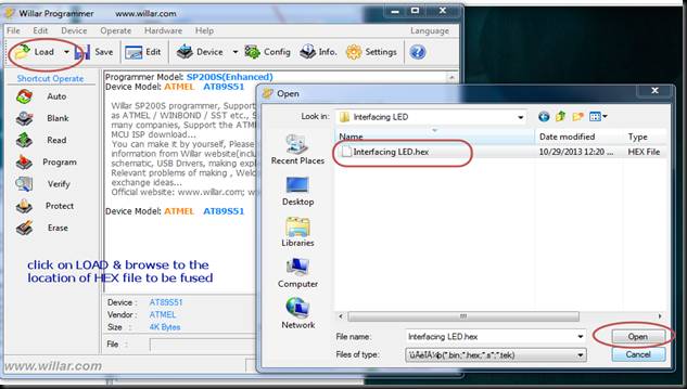
Click on LOAD button & browse to the location of the HEX file to be fused.Select the HEX file & then click OPEN.


g9


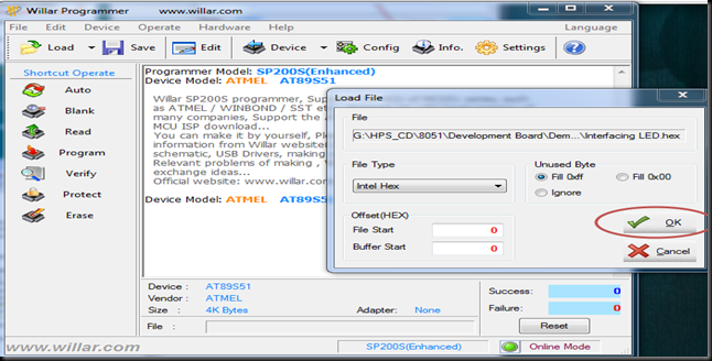
On the next LOAD FILE window leave the File type as “INTEL HEX” & CLICK ok.

g10


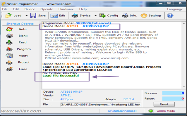
You’ll see LOAD FILE SUCCESSFUL display.

Image 7


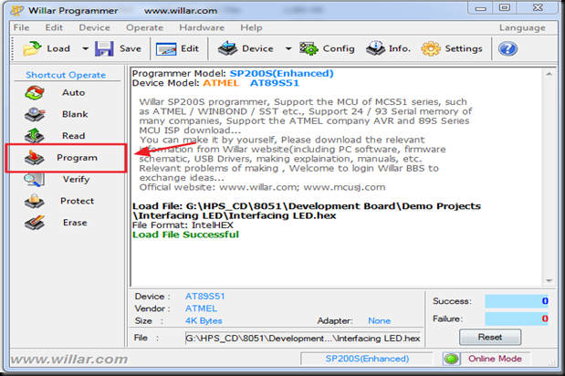
Now click on the PROGRAM button on the left pane.

prog1


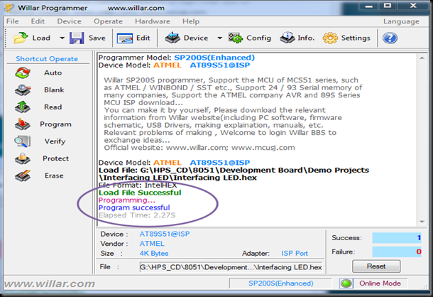
Programming is DONE & you get Program Successful display.

Image 8


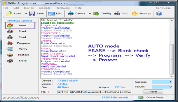
If you click the AUTO mode button , all functions like Erase,Blank check ,Program,Verify & code copy Protect will be done automatically one by one.

Image 9

To test the program loaded , change the switch 2 to ISP OFF position .Push RESET button to see the result of blinking LED .


AVR PROGRAMMER &DEVELOPMENT


Select USB ON (switch 1)

Select the ISP (switch2) to ON position.

Put the Jumper on top of I2C chip to AVR position.

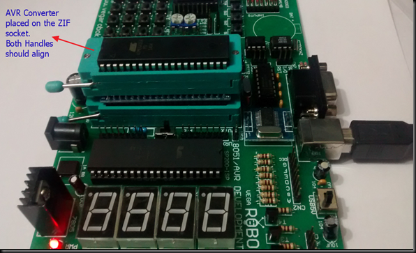
Place the converter socket on the ZIF socket & lock it.Make sure that the handles of sockets match.Do not place the socket in REVERSE as it may damage the target IC.


Image 15

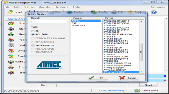
On WILLAR IDE select the DEVICE as ATMEGA16L@ISP 

Ensure to select ISP version of IC & not the plain one.

Image 11


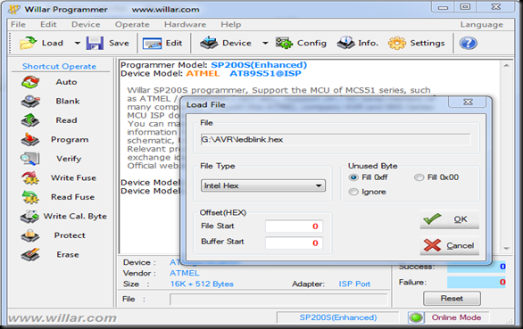
Select File type as INTEL HEX & click OK.


Image 12


Click on LOAD & browse to the location of AVR HEX file .

Click OPEN to LOAD the file.

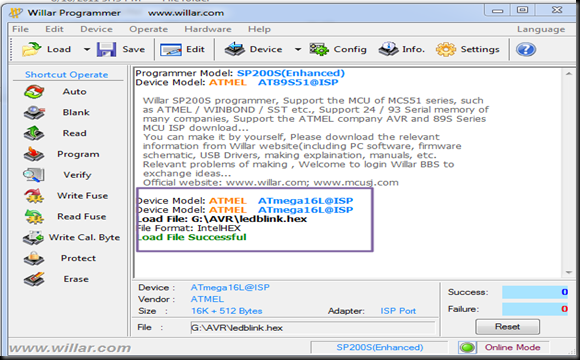
Image 13


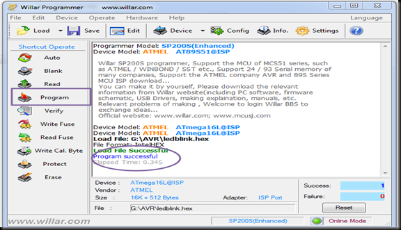
After LOAD SUCCESSFUL display click on PROGRAM to fuse the file.


Image 14


Watch this support video  :


8051 / AVR UNIVERSAL DEVELOPMENT BOARD WITH PROGRAMMER

For availability of this board contact :  


http://www.alselectro.com/8051_avr-2-in-1-development-board-with-programmer-.html


cooltext753793315   cooltext753790696