Archive for April, 2021


The HM-10 BLE Wireless Module-Original is a readily available Bluetooth 4.0 module, which can configure as either Master or slave.

This module is used for establishing wireless data communication. The module is designed by using the Texas Instruments CC2541 Bluetooth low energy(BLE) System on Chip (SoC). You can use it simply for a serial port replacement to establish connection between MCU & your embedded project

It is fully configurable by a rich and well documented AT command-set and allows transparent data communication via serial UART (default baud rate 9600 bps).

The Bluetooth 4.0 HM-10 is basically a breakout board for cc2541, it broke out the LED pins, RX/TX and also adding the voltage regulator that regular 5v to 3.3 v.

Clones available in market have on board only single crystal and the Firmware of clones support limited AT commands.Clones are mostly named as  MLT-BT05

Image 12

Pin Description:

  • STATE: state test pins, connected to an internal LED, generally keep it unconnected.
  • BRK: break connect, it means breaking the Bluetooth connection, generally keep it unconnected.
  • VCC: positive pole of the power source.
  • GND: Ground.
  • TXD: serial interface, transmitting terminal.
  • RXD: serial interface, receiving terminal.
    For testing AT Commands we need an USB-TTL module built on CP2102 ic.
    Connection between HM10 and USB-TTL is shown below :

Image 3

Tx of HM10 can be connected directly to Rx of USB-TTL.

Rx of HM10 to be connected through a level shifter to Tx of USB-TTL. A 1k in series and 2k2 across to Gnd is a simple level shifter.

HM10 can be supplied power 5v , as there is on board 3.3v regulator.

Connect the USB –TTL to PC and note the COM port allotted.

Image 1

We require a TERMINAL software to test AT commands.

The HM10 module do not wait for a Carriage Return .So Putty terminal cannot be used.We use COOLTERM terminal in LINE MODE.

https://freeware.the-meiers.org/CoolTermWin.zip

Install COOLTERM software.

Open OPTIONS

Under Serial port select the COM port of USB-TTL , Baud Rate 9600, 8N1

Image 4

Under TERMINAL setting select LINE MODE.

This allows sending AT commands as a single packet.

Image 3

Click on CONNECT.

Typing AT on the line mode gets an OK reply from HM10.

Image 5

To get the MAC address of HM10

AT+ADDR?

Image 6

Notice the usage of ? for a Query command.

For assignment we do not use =

Just feed in the value after AT command.

For e.g to change the password from default 000000

AT+PASS123456

After PASS we do not use = symbol.Just provide the value.

Image 11

AT+NAME?

Returns the default name of the module as HMSoft.

To change name AT+NAMEmyHM10

ROLE of HM10 by default is SLAVE.

To change to MASTER mode

AT+ROLE1

On Master mode the HM10 will not broadcast its name.Pairing can be initiated only from a MASTER.

Image 7

AT+BAUD?

returns 0.

By default HM10 is in AUTO BAUD mode 0.

You need to set the baud rate by

AT+BAUD9600

AT+POWE?

Returns the transmit power of module which is o dbm by default.

To restart the module

AT+RESET

Image 8

There is an LED connected to PIO1 on board whish shows the STATUS.

Default value is 0 which makes LED blink 500ms  ON/OFF when in disconnected mode.

When paired , the LED goes ON steadily.

Image 9

Now let us pair this module from an ANDROID phone which will be Master.

Install the application BLE TERMINAL.

Open the application and Scan for devices.

HM10 appears as HMSoft.

2021_04_07_18.57.27                                    2021_04_07_18.57.39

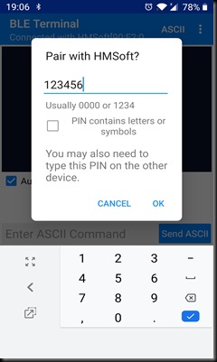
Touch on this HMSoft and provide the password to pair.

2021_04_07_19.06.11                    2021_04_07_19.06.18

Once paired the LED on HM10 glows steadily.

Now you can type some characters on phone which is received at HM10 Coolterm.

From Coolterm window you can type and receive on phone BLE Terminal.

2021_04_07_18.58.49

To DISCONNECT you can touch on the disconnect.

2021_04_07_18.58.56

At the COOLTERM you get the NOTIFICATION.

Image 10

VIDEO TUTORIALS :

blog_image

ESP32-CAM is a camera module based on ESP32. It comes with an OV2640 2 MP camera and provides onboard SD memory card slot.

It is suitable for home smart devices,  wireless monitoring, and other IoT applications.

ESP32 CAM module has on board PSRAM.

Image 2

The OV2640 camera module on the ESP32 Camera board can support a max resolution of 1600 x 1200 pixels, however without PSRAM the camera frame buffer can only support a max resolution of 800×600 pixels

Boards with PSRAM (typically 4MB) can support the max resolution and also support 2 concurrent frame buffers. This provides for a better streaming experience as while  one frame is being sent , the camera is working on capturing the next frame.

PSRAM

Always Power up the module using 5V .Powering the board with 5V increases stability .

Image 1

pins

The camera module has no USB input.So we need a FTDI programmer or USB-TTL module to upload program.In this testing we make use of an USB-TTL module built on CP2102 IC.

Connection between ESP CAM & USB-TTL is simple.

We make use of the 5v power from USB module itself.

Gnd is connected to Gnd pin of Camera module.

Rx of USB module to Tx (printed as UOT) of Camera module.

Tx of USB module to Rx (printed as UOR) of ESP CAM.

c1

Do not use 3.3 V AS POWER SOURCE .

For PROGRAM Mode the GPIO0 pin must be connected to GND.

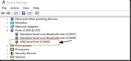
Plug in the USB-TTL module to PC and note the COM port allotted under Device Manager.

Image 1

To use Arduino IDE for programming , we need to install the ESP32 boards Manager for Arduino.

From Arduino IDE open File—> Preferences

Image 2

Copy and paste the following json link for additional Boards Manager :

https://raw.githubusercontent.com/espressif/arduino-esp32/gh-pages/package_esp32_index.json

click OK to close the window.

Image 4

Click   Tools  –> Boards –> Boards Manager

Image 5

A separate window opens.

Search for ESP32 and install the latest version.

Image 6

Once the ESP32 Board package is installed , you can select the ESP CAM board under Tools.

Click Tools  –> Board –> ESP32 Arduino

and select AI Thinker ESP32 CAM

Image 7

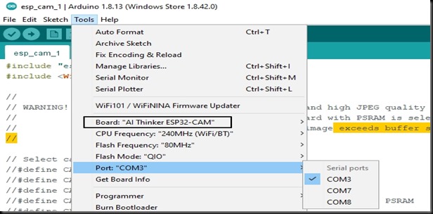
And then select the COM port.

Image 8

Now open the File –> Examples –> ESP32 –> Camera  –> Camera WebServer

Image 9

It is a sophisticated program.

To start with you need to select camera model .

For this , uncomment CAMERA_MODEL_AI_THINKER and comment all other:

Then enter SSID and PASSWORD for your WiFi router.

Image 10

Click on UPLOAD.

If GPIO0 is not connected to GND , you get a fatal error.

Image 11

Ensure that GPIO0 is connected to GND and click Upload.

While you see Connecting…….. at the bottom of IDE , Press the RESET switch on CAM module.

Image 13

RESET switch has to be pressed at the right time while you see Connecting…….

reset

If RESET is not pressed properly , you get Error : Failed to Connect

Image 14

Image 16

Image 18

Once uploading is successful you see the message

Leaving….

Hard Resetting via RTS pin…

Image 20

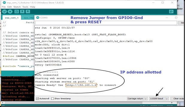
Now open the SERIAL monitor of IDE.

Remove the GPIO-GND Jumper.

and press the RESET switch.

WiFi connected message is displayed  and you get an IP address for your Camera module.

This IP address is Dynamic and provided by your Router.

Image 21

Open the WEB Browser and type in the IP address.

Now you can see the DASHBOARD control of Camera.

Image 22

From here you can click on GET STILL button to take pictures.

Quality & Resolution of the picture can be modified by sliding the control bar provided.

Image 23

START STREAM button is provided to start streaming of live video.

Image 24

While you capture Still pictures , JPG picture details are displayed on the serial monitor.

Image 25

Following are some common problems and solutions :

If your power source is not providing enough current,

you get the following error.

Image 26

Always use 5V for supply , as 3.3v often gives problem.

Image 28

Image 29

If CAMERA MODEL is wrongly selected, you get error : Detected Camera not supported.

Always uncomment the correct model in the code and all others must be commented out.

Image 27

VIDEO TUTORIAL :

blog_image