For HOME AUTOMATION project we use a 4 channel Relay board of 5v Relays.
This is LOW enabled , a LOW at input makes the RELAY ON.
So on start up these input pins must be pulled HIGH.
NodeMCU is loaded with ESPEASY FIRMWARE . You can check this post on how to load.
The Relay board requires a separate power source of 5 volt.
The GND of 5v supply to be made common with the GND of Nodemcu.
RELAY BOARD NODEMCU
IN1 ——- GPIO 16
IN2 ——- GPIO 14
IN3 ——- GPIO 12
IN4 ——- GPIO 13
DOMOTICZ Service is running on Raspberry PI which is on the same LAN as my PC.
The Domoticz server is accessed by typing in the RPI’s IP address followed by port no. 8080
192.168.0.150:8080
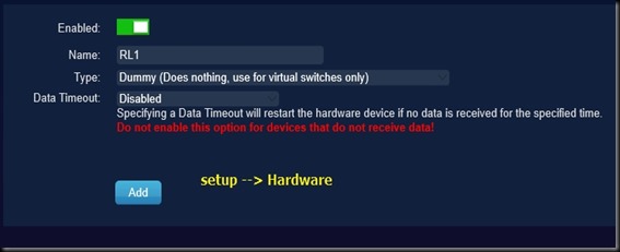
Click on Setup – > Hardware and create Type DUMMY for Relay 1 , name it as RL1.Click ADD
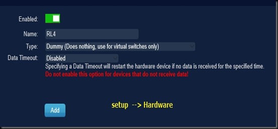
Same way create 3 more Type Dummy for other 3 Relays RL2, RL3 & RL4.
On top a list of Types created is displayed.
Click on Create Virtual Sensor for RL1.
Select Sensor type as SWITCH and name it as RL1.
Similarly create Sensor type Switches for other 3 , RL2,RL3 & RL4
Under setup –> Devices all the 4 switches are listed out with INDEX (IDX) numbers.
Note these IDX numbers , as we have to set the same IDX number in ESPEASY Setup.
Under SWITCHES tab you can see the VIRTUAL SWITCHES created.
Click on EDIT button on RL1
Switch ICON is a bulb by default.You can select any one from the drop down list.
Under ON Action feed in the IP address of ESPEASY with HTTP command
http//192.168.0.110/control?cmd=gpio,16,0
Note the usage of 0 for ON , as the relay board is LOW enabled.
Against OFF action
http://192.168.0.110/command?cmd=gpio,16,1
Click SAVE
Same way click on other Relay switches EDIT button and feed in the HTTP command including the correct GPIO number.
Once the HTTP commands are saved , you can go to ESPEASY Dashboard by typing in the IP address on browser.
Here mine is 192.168.0.110
Under CONTROLLERS select the protocol as DOMOTICZ HTTP
Provide the IP address of DOMOTICZ and its port no. 8080
Click ENABLED.
Under HARDWARE make the GPIO pins used to OUTPUT HIGH on Boot.
As the RELAY Board is LOW enabled , this is necessary.
GPIO16 by default is HIGH on Boot , so there is no settings for GPIO 16.
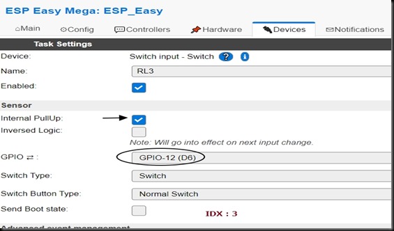
Under DEVICES select the DEVICE as SWITCH INPUT – SWITCH
Provide a name RL1
Click ENABLED.
RL1 is connected to GPIO 16 , select it.
Provide the IDX number as 1.
Internal pull up is similar to OUTPUT HIGH , not needed for GPIO 16.
As done for RL1 repeat for other relays
RL2 –GPIO14 , iNTERNAL PULL UP –Yes, IDX 2
RL3 –GPIO12 , iNTERNAL PULL UP –Yes, IDX 3
RL2 –GPIO13 , iNTERNAL PULL UP –Yes, IDX 4
Now all the settings are done.
Go to DOMOTICZ Dashboard and click on SWITCHES tab.
From here you can Switch ON OFF the relays and the load connected to it.
VIDEO :


