Category: BlueTooth/WIFI


Image 2


Image 1


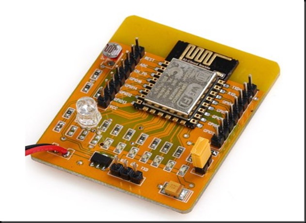
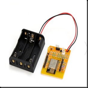
Introducing a new ESP8266 Development Board with an ESP-12, a 3x AA battery holder, a voltage regulator, an RGB LED, several red LEDs, and a light sensor LDR on the ADC input all on one board.

The board can be controlled by an open source Android App which is available from the AI-THINKER Website.

GPIO pins are extended with berg pins for easy external connections. RXD,TXD & GND pins are provided for programming / firmware upgrading. A yellow jumper is provided to pull GPIO0 pin to GND during programming. During normal operation this jumper must be removed.

The board is powered by 3 nos AA batteries , for which a battery box is already wired. On board 3.3v regulator is provided for a stable power supply.

No power switch or Reset switch is provided. To switch off you need to pull out one of the batteries.

The board comes pre-loaded with a demo which does actually seem to work.  If you have an Android based phone or tablet you can download AI-Thinker’s app to control and mix the color balance on the RGB LED and to switch the other LEDs on and off.

The Android Application can be downloaded from :

https://play.google.com/store/apps/details?id=com.duvallsoftware.iotdemoapp


There are also 6 red LEDs fixed with the necessary resistors connected to GPIO16, GPIO14, GPIO5, GPIO4, GPIO0 and GPIO2. A BLUE LED is always ON if the board is powered.

The GPIO13, GPIO12 and GPIO15 are connected to a RGB LED which allows you color mixing using PWM.

ADC

The analog-digital converter is also available on a pin & connected to a light resistor. This lets you quickly test the ADC and you still can clip the resistor off if you want to measure another analog source.Remember the range of ADC is max 1v & not 0 to 3.3v

If you don’t want to use the light sensor or the LEDs you can simply clip them off. Then you’ll just have an  ESP8266 with 3xAA power supply, 9 available GPIO pins and one ADC.

On the playstore of your Android device search for  IOT DEMO App & install it.

Open the Settings & enable WIFI of the Android phone.Now power on the ESP board to see the AI-THINKER SSID on your mobile.

PAIR this with the ESP board using password ai-thinker

Now open the app & touch on LED 1 to 6 , to see the corresponding light glowing on the ESP board.On the top you can see 3 icons with sliders in the App. Use this to mix colors on the 3 color LED of ESP board.

Once the functioning of board is verified , you can proceed to connect the GPIO pins of ESP board with a 4 channel Relay board.

The 4 channel relay board used requires a separate power source of 5V, 1amp.For demo 2 of the GPIO pins are connected to relay 1 & relay 3.The GND pins of both ESP & the Relay. board to be made common.

You can watch this video to learn the home automation basics with ESP board :


cooltext753793315    cooltext753790696

ESP8266 WIFI Module comes with an inbuilt firmware which supports serial interface and can be controlled using AT commands. Even though we can use this module to offer WiFi functionality from another micro controller ,this module is not just a simple serial to WiFi transceiver .

It is comprised of  a 32Bit processor ( 80MHz) ,  512KB SPI FLASH , 64KB SRAM ,96KB DRAM , GPIO Pins & WIFI Transceiver.

In this post I shall walk you through how to upgrade new Firmware on to the ESP module.This procedure can also be followed in case  esp8266 stopped working , or giving out some random garbage data.

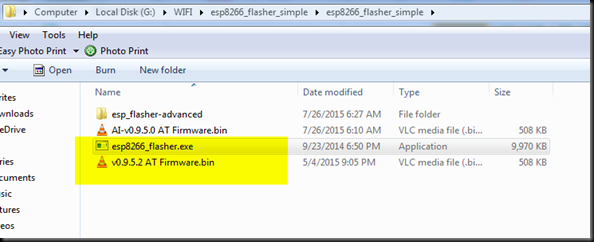
Before starting upgrading I downloaded following 2 files .

http://tinyurl.com/pohvwfh

http://www.alselectro.com/files/esp8266_flasher_simple.zip

1. ESP SIMPLE FLASHER – FLASH DOWNLOAD TOOL

2. FIRMWARE latest BIN file  version 9.5.0

image2

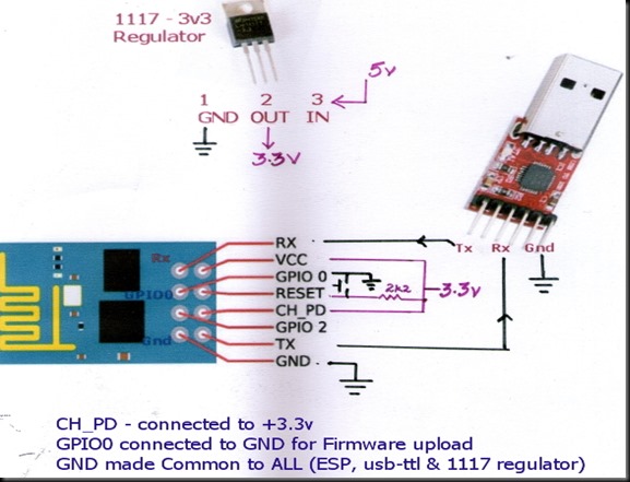
I used a  USB – TTL converter between my ESP-01 board & PC. As the ESP device requires 200ma current which cannot be sourced from USB-TTL module , I used a separate power source 5v/1Amp adaptor followed by a 3.3v regulator ( 1117 3.3v).

Please note that while I used a separate power source for ESP module , the operation was smooth.

I connected the ESP module with USB-TTL board as per following wiring diagram :

Image 2

CH-PD is CHIP ENABLE which is directly connected to +3.3v

RST is pulled HIGH through a 2k2 resistor.A press switch is connected to GND , so that when it is pressed RST pin is grounded.

TX of ESP is connected to RX of USB-TTL module

RX is connected to TX .

Vcc is connected to +3.3v of the external Regular. GND is made common for all , i.e GND of ESP ,USB-TTL & that of 1117 regulator are ALL MADE COMMON.

GPIO0 pin is connected to GND to upload firmware.

After uploading firmware , this GPIO0 connection must be removed from GND.

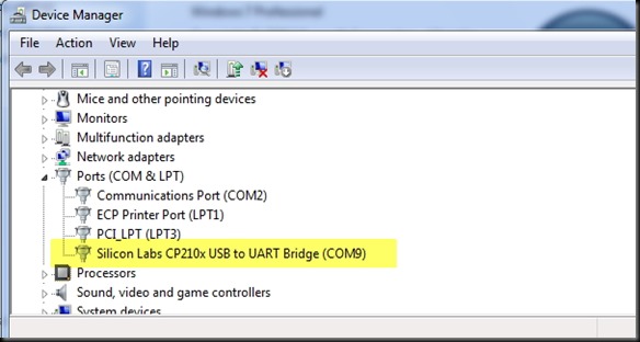
The USB-TTL converter I used is built on Silicon Labs CP2102 chip which is highly reliable one.The other type available in the market is built on Prolific chip (Chinese one , not original) , which has got some issues with driver installation .

I connected the USB-TTL board to my PC & from the Device Manager I noted the Port allotted .

COM port COM9 is allotted.

Image 4

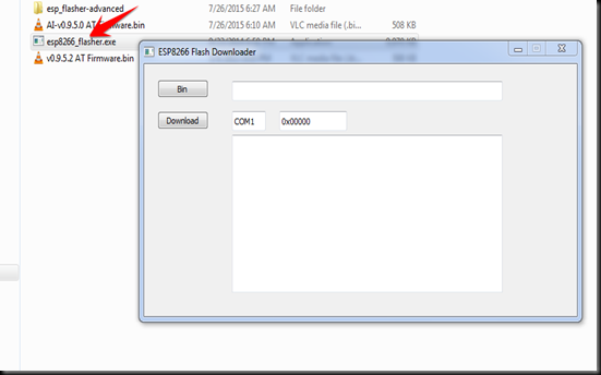
Next , I browsed to the folder where I’ve already downloaded the 2 required files , one is the simple flasher & the other one is the latest firmware to be uploaded.

On double clicking the esp8266_flasher .exe file , I got this Downloader window open

image3

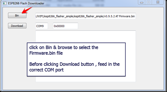
I clicked on the BIN button & browsed to the location of the folder to select firmware.bin file.

Before clicking the DOWNLOAD button I changed the COM port number , where USB-TTL is connected to PC.

The default address 0x000000  is automatically displayed after COM port

image4

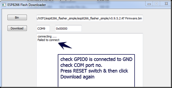
First time when I clicked the Download button I got “Failed to connect”   error.

This was because I’ve connected GPIO0 to GND after the power to ESP board is ON.

GPIO0 pin must be at GND level when the power is initially provided to the ESP module.

image5

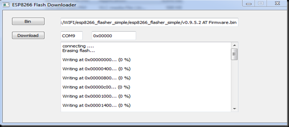
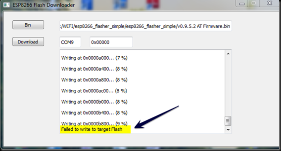
Second time when I clicked on the Download button , Writing started  but abruptly failed .

image6

You can see the “Failed to write to target Flash” message in the screenshot below .

image7

After repeated trials I finally found that , connecting 100uf capacitor between Vcc & Gnd

solved the problem.

image8

Finally I hit the Download button and waited for the flashing process to complete. The STATUS BLUE LED blinked fast while the uploading was going on.

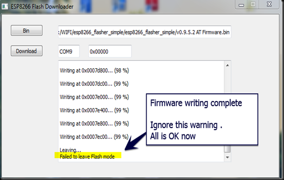
“ Failed to leave Flash mode “ message after 99% writing ,does not affect the flashing process in any way and can be ignored.

After the firmware flashing, ESP8266 module settings changed. The default baud rate now is 9600 & can be modified using AT+CIOBAUD command.

It is even possible to cloud update ESP8266 Wi-Fi module firmware using AT+CIUPDATE command.But I suggest you not to try this cloud update , as it’s got some issues.

Now I removed GPIO0 pin from GND & pressed RESET switch & then closed the Flasher application.

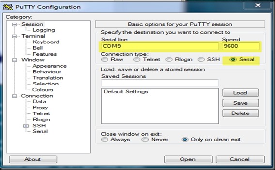
I opened the terminal software Putty & selected Serial COM Port 9 & baud rate 9600.

Image 5

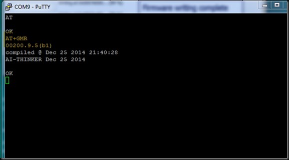
I typed in AT command & got an OK response from the ESP module.

AT+GMR returned the upgraded firmware version 9.5.

Image 6

Watch this support Video :

cooltext753793315     cooltext753790696

After struggling for nearly a week with MTS dongle , finally I found an excellent solution to enable PORT FORWARDING.

HUAWEI POWER FI  E8221 model dongle  is the solution I found.This dongle accepts any data SIM for internet connectivity & we can create a WIFI HOTSPOT with this dongle to connect max. of 10 devices.

Further it has got a VIRTUAL SERVER setting tab in the configuration , thus enabling Port forwarding.

There is no need of an external Router like TP-LINK (which I used with MTS , as seen in my previous post).

1

I’ve inserted a BSNL DATA SIM into the HUAWEI dongle for Internet connection.

The DEFAULT GATEWAY IP address while using Huawei is 192.168.8.1

This can also be found by opening CMD in Windows search bar & then typing the command IPCONFIG /ALL

Typing this Gateway address in the browser , you get the HUAWEI CONFIGURATION window.Here the service provider (for me BSNL ) name is displayed with connection status.

Image 1

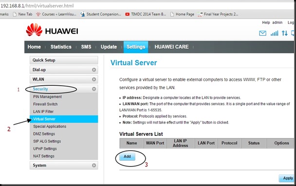
Click on CONNECTION SETTINGS seen below the “Connected” status.

On left pane , under SECURITY tab select the VIRTUAL SERVER.

Before clicking the ADD button under VIRTUAL SERVER LIST , we’ve to configure the ESP module & start a SERVER on port 333.

Image 2

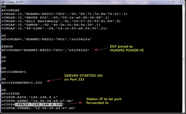
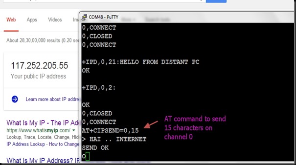
The ESP 8266 module is connected to PC through USB-TTL board & the COM port allotted in my PC is COM 48 .

I’m using PUTTY terminal software to communicate with this COM port.

Following is the screen shot on which you can see the AT commands used to connect ESP with HUAWEI on WIFI , & starting a server on port 333.

The selection of port is random.You can select any port within 65536 , except the standard ports like 80 (HTTP) ,  21 (FTP), 23 (TELNET) ,etc..

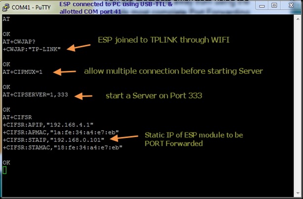
AT+CWLAP   – to list the surrounding Access Points near ESP module

AT+CWJAP=”ssid”,”password”   – to join the AP using the SSID name & its password.

AT+CIPMUX=1   — to enable Multiple connections before starting server

AT+CIPSERVER=1,333   –  to start a server on port 333

AT+CIFSR  –  displays the IP address . STAIP is the IP address we need to port forward.

Image 3

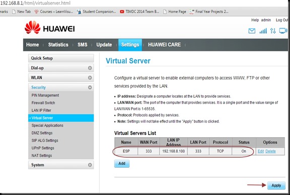
After starting the server on ESP8266 , we need to port forward under the HUAWEI configuration.

Click on the ADD button , seen under VIRTUAL SERVER LIST.

Fill in details as below :

Name  : ESP

WAN Port : 333

LAN IP   : 192.168.8.100

LAN Port  ; 333

Protocol : TCP

Status  : ON

Finally click on APPLY.

Image 4

Needless to say , you’ve to apply an INBOUND RULE on Windows Firewall settings to allow this port 333 . (check the previous post on how to do this).

The external world can contact this ESP only through the EXTERNAL IP address.To know the IP , just type in WHAT IS MY IP on Google .In my case it is 117.252.205.55

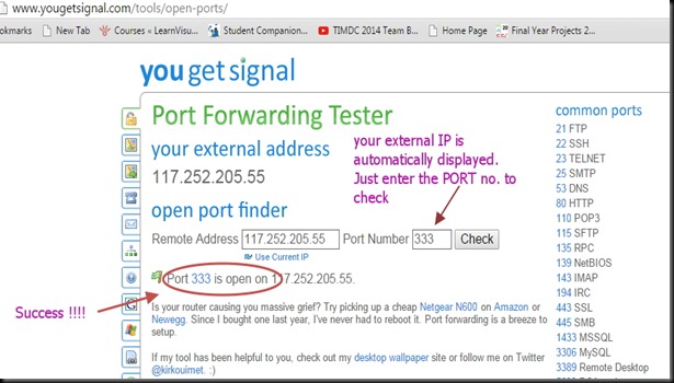
To confirm that the PORT 33 is open & listening , visit the online tool www.yougetsignal.com

You need to test this on the PC where you’ve connected the ESP module.

The external IP will be automatically displayed.You just  type in the port no. to verify.

Following screen shot shows that my port 333 is open

Image 6

Now we’re all set to contact ESP from outside World.

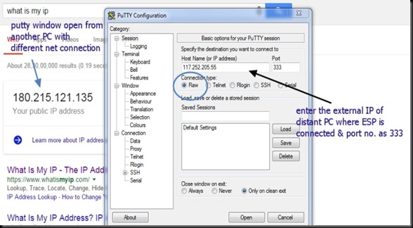
From a distant PC with different Internet connection , open a PUTTY terminal.

Select RAW as Connection type & type in the IP 117.252.205.55  & port no. as 333.

Following screen shot shows the PUTTY terminal which I’ve opened on a different PC with a different IP.

Image 5

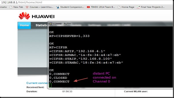
On clicking OPEN button , the ESP Terminal at the other end will respond with

0,CONNECT

This means a connection established on channel 0.

Image 8

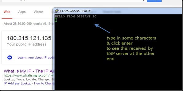
Now type in some characters on the distant PC terminal.

newip2

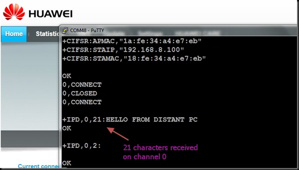
The ESP terminal responds with

+IPD,0,21:characters received

which indicates , it has received 21 characters on channel 0.

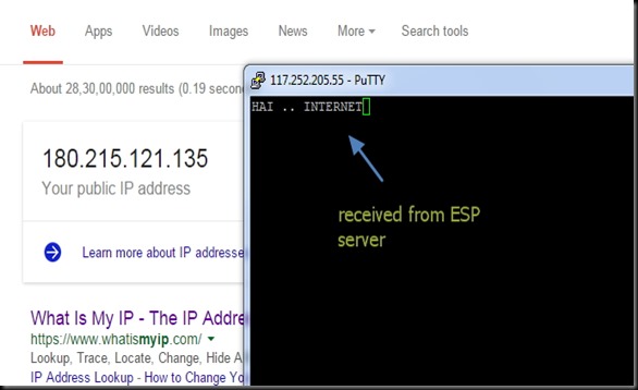
The screen shots with HUAWEI symbol (IP 117.252.205.55 ) is that of TERMINAL where ESP module is connected & the screen shot of distant PC is shown with the IP address 180.215.121.135

Image 9

To send characters from ESP , use the AT command :

AT+CIPSEND=0,15

This indicates that you want to send 15 characters on channel 0.

The ESP will respond with a > symbol & waits till you type 15 characters.

Image 10

The distant PC now receives the 15 characters you typed inside ESP terminal.

newip3

Hence a two communication is established with ESP Terminal & a PC from anywhere in the world.This opens the door for INTERNET OF THINGS where you can control the devices connected to ESP from anywhere in the World.

WATCH THIS VIDEO :

cooltext753793315    cooltext753790696

In the previous post we’ve seen the ways to control the ESP8266 WIFI module from anywhere in the world.The key to success depends on the PORT FORWARDING , where we route the contact on particular port to the local IP address of the WIFI module.

Nowadays USB dongles are used widely for internet access .This post will help you troubleshoot PORT FORWARDING.

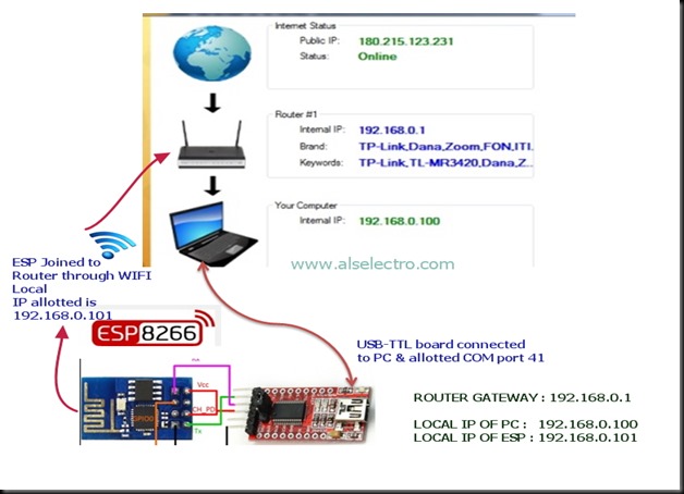
Following is the SETUP diagram .

TPLINK ROUTER is on the top of the NETWORK. An MTS USB dongle is plugged to TPLINK Router (model TL-MR 3420 with 3G/4G support).

A Laptop is connected to TPLINK Router on Ethernet using RJ45 cable.

A USB to TTL board is connected to PC on which the ESP 8266 module is wired.

The ESP module is linked to TPLINK Router on WIFI using the AT Command AT+CWJAP=”SSID”,”password”


ip8

On switching ON the ROUTER , it assigns LOCAL IP address to the modules connected to it either on RJ45 (wired) or on WIFI.

In our set up the LAPTOP which is connected by wire is assigned 192.168.0.100

& the ESP module which is connected on WIFI is assigned 192.168.0.101.

Note that the allotment of address is on first come basis.When you power off & on the Router again , this allotment may vary.

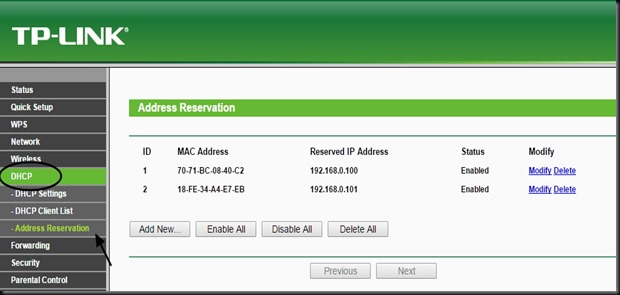
You can RESERVE the address by selecting the DHCP tab of TPLINK configuration.Here select

Address Reservation & then feed in the MAC address of the devices you’ve connected to the Router.

To know the MAC address you can use the ADVANCED IP SCANNER TOOL.

Download & install the tool. Start the scanner to know the IP address & MAC address of the devices connected .

ip12

STEP 1:

Confirm that you’ve Internet access after plugging  the USB dongle to the TPLINK Router .You need to login the TPLINK configuration with address 192.168.0.1 & enter the QUICK SETUP for this process.

STEP 2 :

Start the SERVER on ESP module

ip2


STEP 3 :OPEN PORT SCANNER

To confirm that the port we’ve started server ( here port no. 333) is OPEN , we use a  port scanner tool .

Advanced Port Scanner is a small, fast, robust and easy-to-use port scanner for Win32 platform. It uses a multithread technique, so on fast machines you can scan ports very fast.

Also, it contains descriptions for common ports, and can perform scans on predefined port ranges.

Download it & install.

http://download.cnet.com/Advanced-Port-Scanner/3001-18508_4-98269.html?hlndr=1&part=dl-73294

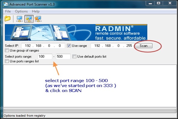
Open Port scanner & under Select port range enter 100 to 500 . As we’ve to check port 333 , we enter the range below 500 .Click on SCAN .

IP4


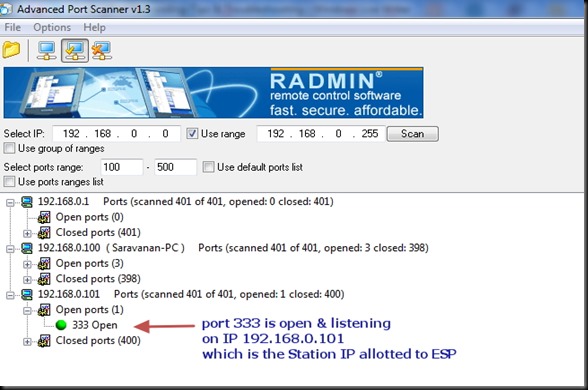
The PORT SCANNER displays the result regarding status of PORTs of your PC as well as the module connected to PC.

Here we can confirm that port 333 is OPEN on IP 192.168.0.101 (ESP module).

 ip5


STEP 4 : SET UP FORWARDING RULE on TPLINK CONFIGURATION

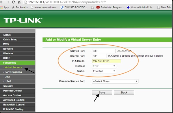
On TPLINK configuration window , under FORWARDING select the tab VIRTUAL SERVERS.

Click on ADD NEW.. & enter the Service & Internal port as 333 .

IP Address as 192.168.0.101 , which is the local IP allotted by Router to ESP module.

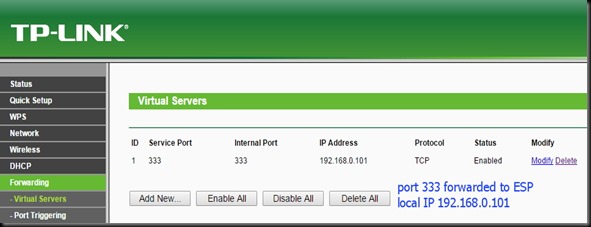
Select Protocol as TCP & then SAVE the settings.


IP9


IP 10


STEP 5 : WINDOWS FIREWALL SETTINGS

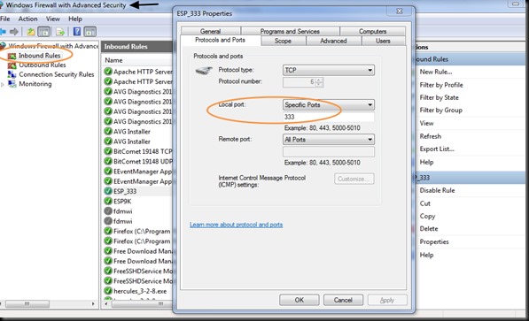
Open Windows Firewall Advanced settings & click on INBOUND RULES.

SET the rule to allow communication on port 333.

IP11


Now you are set to check the condition of PORT 333 externally.

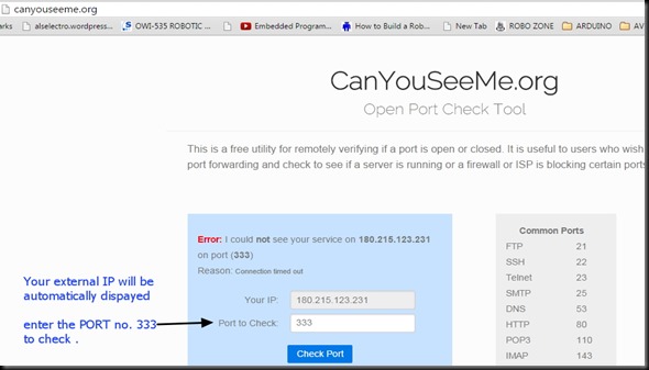
For this we make use of an online tool www.canyouseeme.org

On opening the site your external IP will be automatically displayed.Enter the port number to check.

Click on CHECK PORT.

ip 13

Unless you see SUCCESS on this test , you can’t contact your ESP module from external world.

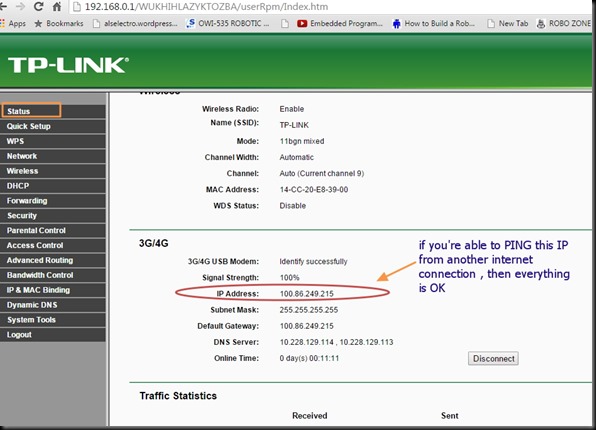
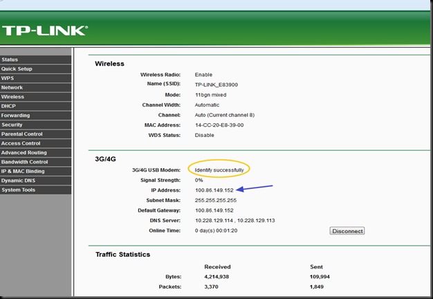
If you get ERROR , open the TPLINK configuration & click on STATUS.

Note IP Address displayed under 3G/4G.

From another computer with a different internet connection try to PING this IP address.

Open CMD & type in PING x.x.x.x

ip1


If the PING result is OK , you can be sure that the ESP module can be contacted from outside world.

If the PING result is TIMED OUT , you can’t communicate with ESP.

The   STATUS tab in my case , as shown in above screen shot , indicates an IP address starting 100.86.x.x

Generally following IP address ranges are PRIVATE IP ADDRESS RANGES :

10.x.x.x

172.16.x.x

192.168.x.x

These are reserved by IANA for private Intranets & NOT ROUTABLE TO INTERNET.

Private addresses are not reachable on the Internet. Therefore, Internet traffic from a host that has a private address must either send its requests to an Application layer gateway (such as a proxy server), which has a valid public address, or have its private address translated into a valid public address by a network address translator (NAT) before it is sent on the Internet.

In my case , the MTS ISP provider hide the PUBLIC IP address.

The MTS dongle does not support VIRTUAL SERVER settings , which means PORT FORWARDING IS NOT POSSIBLE with MTS.

What I couldn’t understand was , while writing my previous blog ,it worked sometimes.While MTS customer support was contacted repeatedly , they finally accepted that port forwarding is blocked by them.

After sleepless nights I’ve found a solution….. Read on my next post ….


cooltext753793315    cooltext753790696

Link to previous posts 1.AT Commands2. TCP Client/Server  , 3. Connect to Android


In the previous posts we’ve tested the WIFI module in TCP Server/Client mode & how to control from an Android mobile.These are related to LAN – Local Area Network where the WIFI module & Mobile are connected to the same ACCESS POINT (AP).

The AP  I’ve used is a WIFI Dongle MTS MBLAZE. For the outside world to contact the ESP module connected to MTS , PORT FORWARDING should be done. This is a method by which the IP address of ESP module is forwarded , so that any one accessing the particular port of external IP will land on the ESP module.

The problem is WIFI Dongles do not allow Port Forwarding  . As I’ve previous experience in CCTV  DVR port forwarding  (you can watch my video on DVR port forwarding Here )  using land line Internet connection , I decided to apply the same technique for ESP WIFI.

No Internet Dongle allows port forwarding. TPLINK MR3420 Wireless 3G/4G Router came to my rescue.
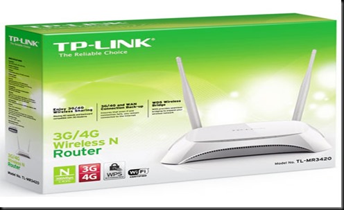
TL-3420-800x800

Following are the tasks we need to do :

1.Configure TPLINK ROUTER  to accept 3G Internet Dongle

2.Connect ESP to TPLINK on WIFI & Start a SERVER on port 333

3.PORT FORWARDING ESP’s IP on TPLINK ROUTER CONFIGURATION

4.WINDOWS FIREWALL SETTINGS

5 :Know your External IP & Port Open Condition

6.Connecting from a Distant PC anywhere in the World


STEP 1.CONFIGURE TPLINK TO ACCEPT 3G DONGLE

The TPLINK Router accepts USB Dongle as well as WAN connection.I plugged in my MTS dongle to the USB port of TPLINK.

One of the Ethernet ports is connected to the PC using RJ45 cable.

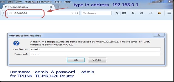
To configure the Router , open the browser & type in the Address of the Router .The IP address is 192.168.0.1

Both user name & password is admin
tp1

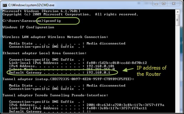
To know the Routers IP , you can type in CMD to open Command window .

After the prompt type the command “ipconfig” .The Default Gateway address is the IP of Router.
cmd1

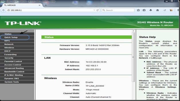
The configuration window of Router appears.

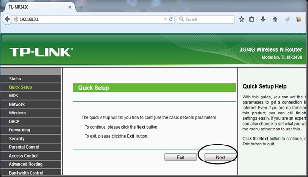
Select “QUICK SETUP”
tp2

Click Next button.

tp3

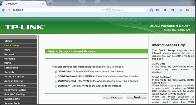
Select Internet access mode as “3G/4G ONLY”.
tp4

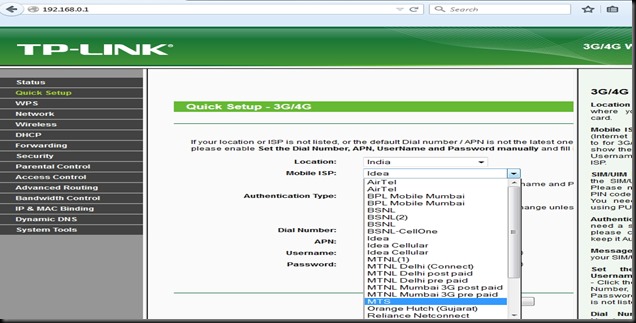
Select your Mobile ISP from the drop down menu .Mine is MTS .
 

tp5

Rest of the settings you can leave it for defaults.

tp6

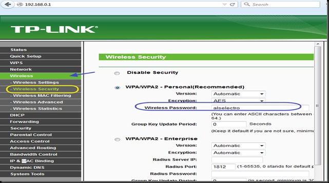
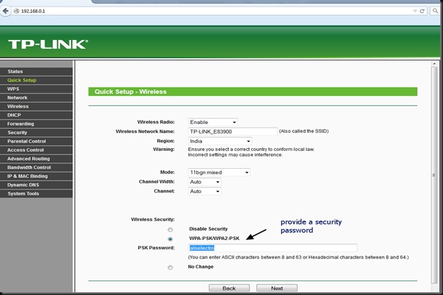
Click NEXT  & under Wireless Security select WPA2_PSK mode & provide a password.
tp7


tp13

Click Next & then FINISH to complete the quick setup.
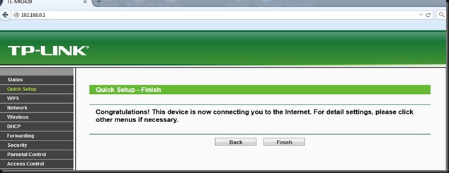
tp8


Under Status  you can see the 3G/4G USB Modem as Identified Successfully
tp11


For now the TPLINK Configuration is completed.We shall connect the ESP WIFI to TPLINK Access Point , Start a Server on ESP Module & again come back to TPLINK to configure PORT FORWARDING.


STEP 2 : Connect ESP to TPLINK on WIFI & Start a SERVER on port 333

We make use of Putty Terminal software to communicate with ESP module.

You can download PuTty here.

Open Putty & select Serial .Feed in the COM port where ESP is connected (through USB –TTL board) & select the Baud rate as 9600.

Now if you type in AT , you get OK response.

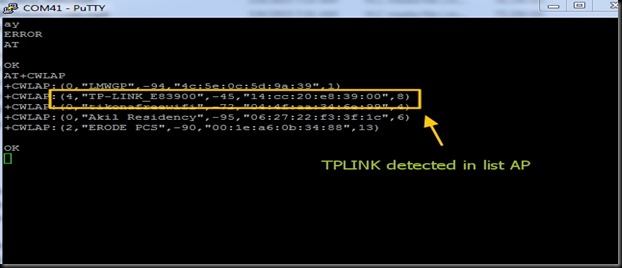
From the Putty window ,search for the surrounding Access Points (AP) using the command

AT+CWLAP

You can see the TP-LINK under listed APs.
tp12


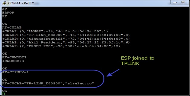
Join TPLINK AP using the password we’ve setup already with the Router.

AT+CWJAP=”TP-LINK_E83900”,”alselectro”
tp14

For allowing multiple connections

AT+CIPMUX=1

Now start a SERVER using command AT+CIPSERVER

You can use any port no. within 65536 , except the standard allotted ports like HTTP (port 80), FTP (21) , Telnet (23) , etc.,

The default server port for ESP is 333.Let us start a Server on that port using command :

AT+CIPSERVER=1,333
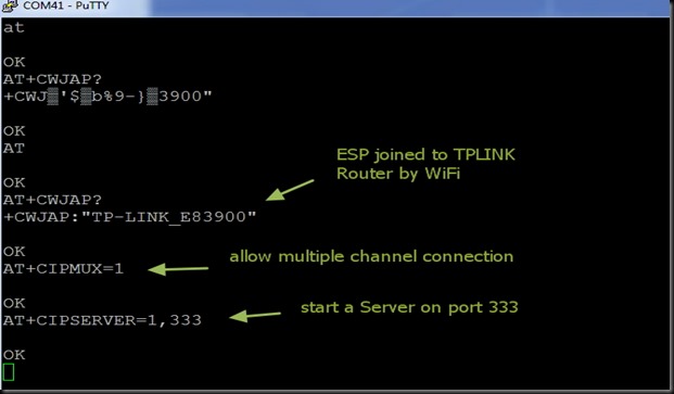
 

tpnew1

To know the Station IP  type in

AT+CIFSR

This returns the Access Point IP & the Station IP.

If CWMODE =1 , you get only the STAIP. Default is CWMODE=3 , which gives both IPs.

The STATION IP here is 192.168.0.100

tpnew2


This Station IP is an Internal IP & cannot be contacted from outside world.To enable contact this IP , we need to PORT FORWARD .

As we’ve started a Server on port 333 , we shall forward any contact on this port to the Station IP.


STEP 3 : PORT FORWARDING ESP’s IP on TPLINK ROUTER CONFIGURATION


Open the TPLINK configure window which we’ve opened initially, by typing in 192.168.0.1 (IP of TPLINK Router ) , username & password both are –  admin

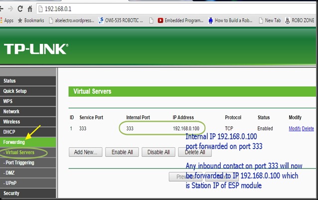
Under FORWARDING select VIRTUAL SERVERS

Click on ADD NEW..
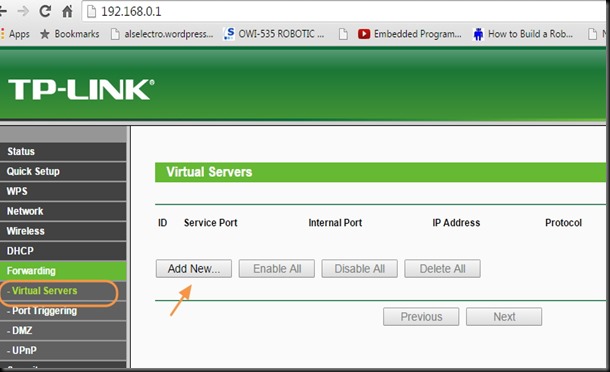
tpnew9

Enter the Service port as 333 , as we’ve started a server on this port on ESP.

Fill in IP address as 192.168.0.100 , which is the Station IP of ESP.

Select Protocol as TCP & Status Enabled.

Click on SAVE . The Internal port will be assigned same as Service port automatically.
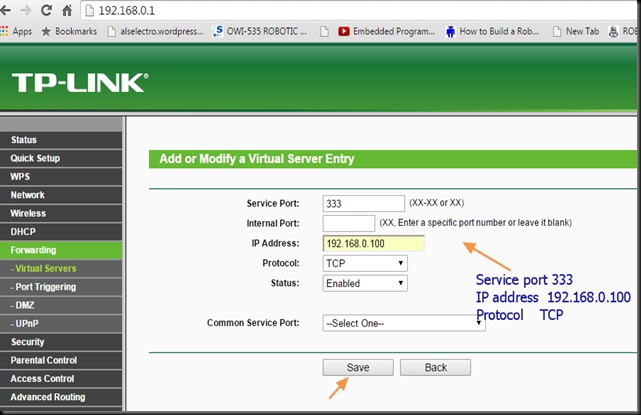
tpnew10


tpnew3


Now we need to allow this port for incoming traffic on the Windows Firewall settings.


STEP 4: WINDOWS FIREWALL SETTINGS :

Type in FIREWALL on Windows search bar & select “Windows Firewall with Advanced Security “
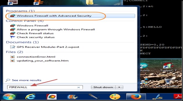
 

tp27

Select “INBOUND RULES “ on the left pane.
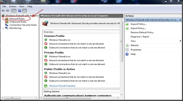
 

tp28

Click on “NEW RULES” on the right Actions pane
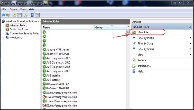
 

tp29

Select PORT as Rule type on the next screen.
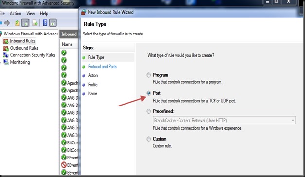
tp30

Select Protocol as TCP & enter the port number 333  under Specific Local Ports.
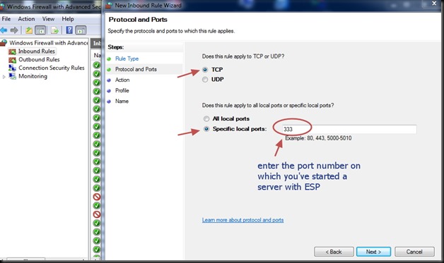
 

tp31

Select “Allow the Connection “.

tp32

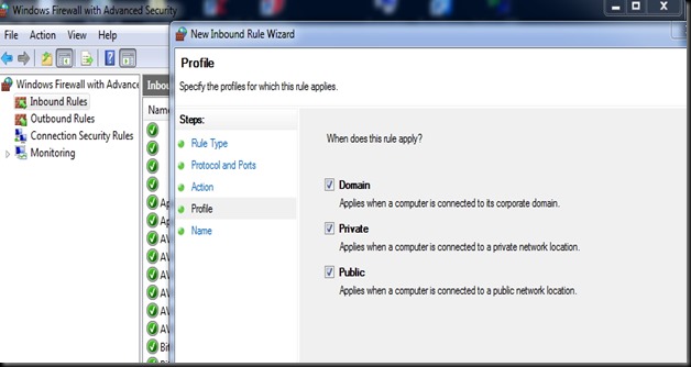
Apply rule to all  Domain,Private & Public.
tp33

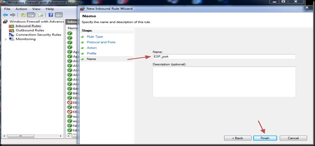
You can name the rule & click Finish to save it.
tp34

STEP 5 :Know your External IP & Port Open Condition

The Router is accessed from outside world by its external IP. This external IP is assigned by the ISP provider.Generally this IP is DYNAMIC ,which means every time you switch on your Router , a different IP is assigned.

For a fixed IP , you’ve to contact your ISP provider & pay for a STATIC IP.

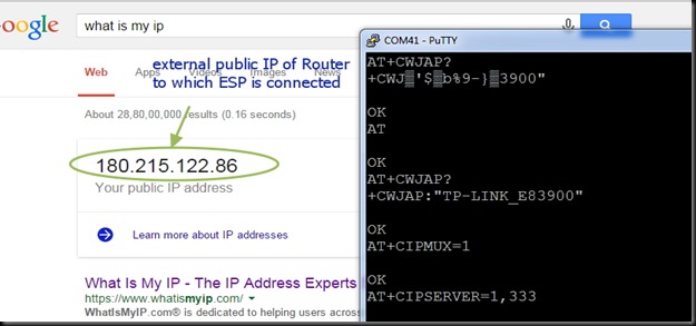
Open your web browser & Google for “ what is my ip “

Your public IP address will  be displayed.Note that down.
tpnew4

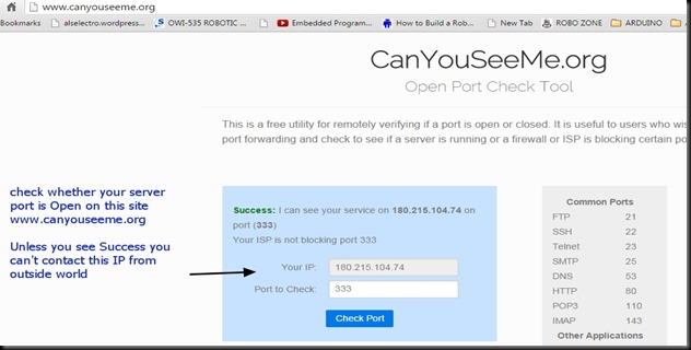
Now we shall check whether the port 333 is open or not.

Visit the site  www.canyouseeme.org

Your IP will be automatically displayed.Under  “ Port to Check “ enter the port number 333

& click on CHECK PORT.

You see SUCCESS message only on following conditions :

1. Router TPLINK Port Forwarding setting is done so that incoming request on port 333 is forwarded to the Station IP of ESP.

2. Windows Firewall setting Inbound Rule is set to allow communication on port 333.
 

tpnew5


Only on getting  SUCCESS message under Canyouseeme.org you can proceed further.

Till now all settings & configurations are done on PC connected with TPLINK & ESP.

Next is the final step in which another PC is involved from anywhere in the world.


FINAL STEP 6 : Connecting from a Distant PC anywhere in the World


For demo purpose I’m using a separate PC with a different Internet connection.

You can see from screen shot below the IP address of the distant PC.

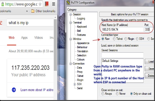
Open Putty window in that PC & select RAW as Connection type.

Feed in the External IP address to be contacted (that of ESP ) & enter the Port no. as 333
TPW3

After entering the details , click on Load button.

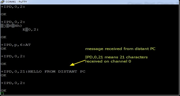
Immediately you get response on the Putty window of ESP , like ,  +IPD,0,2:

From distant PC Putty window type in some characters .This will be received in the ESP window.
 

tpnew6

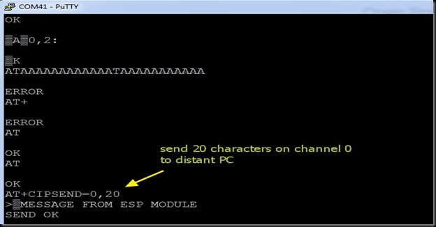
To send data from ESP , use command :

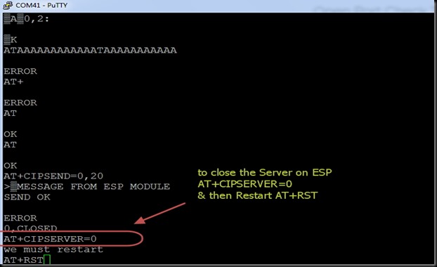
AT+CIPSEND=0,20

This command waits for you to type 20 characters to be sent on channel 0.
tpnew7

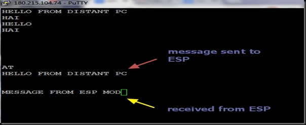
The following is the screen shot of Distant PC Putty window.

Note the IP address of distant PC on top of putty window.
TPW5


To close the Server on the ESP side , use command :

AT+CIPSERVER=0

& then Restart using AT+RST
 

tpnew8


Once you know the external public IP address of the Router & the Port number on which the server is started, you can contact this ESP from anywhere in the world !!!!


cooltext753793315     cooltext753790696

In the previous post we’ve seen how to initiate ESP module & use AT commands.In this post TCP CLIENT mode operation is explained.

ESP8266 WIFI module has 3 modes of operation.

ST  – Station mode in which ESP acts as a device & connects to an existing Access point.

AP – Access Point mode where the ESP itself acts as AP & other devices like Mobile can connect to it.

Both – ST & AP both mode is allowed in ESP.The mode of operation is set by the AT command

AT+CWMODE = 1 for ST mode , 2 for AP mode & 3 for both.

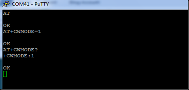
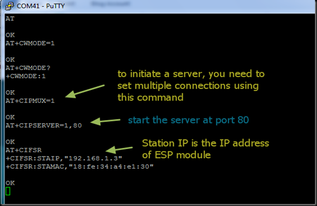
As we’re testing ESP on STation mode , issue the command

AT+CWMODE=1

Image 7

To communicate with a webpage , we need to start a server with ESP module.You need to set multiple connections using command

AT+CIPMUX=1

This initiates the server for a Webserver.

Next we start the server at HTTP port 80 using command ,

AT+CIPSERVER=1,80

Image 8

To close the server the command is AT+CIPSERVER=0 followed by a Reset AT+RST

To get the STATION IP address ,

AT+CIFSR

The module returns the Station IP address , 192.168.1.3 .

If the CWMODE is set to 3 , you’ll get 2 IP address , one for AP & another for Station mode.We need the station IP address for Client mode operation.

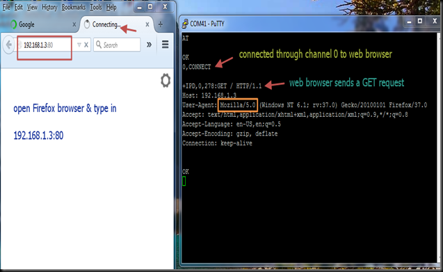
Open your web browser & type in the address 192.168.1.3

The browser sends a HTTP GET request which is displayed on the putty window where ESP module is connected.The host IP address & the user agent (your web browser name) are displayed.

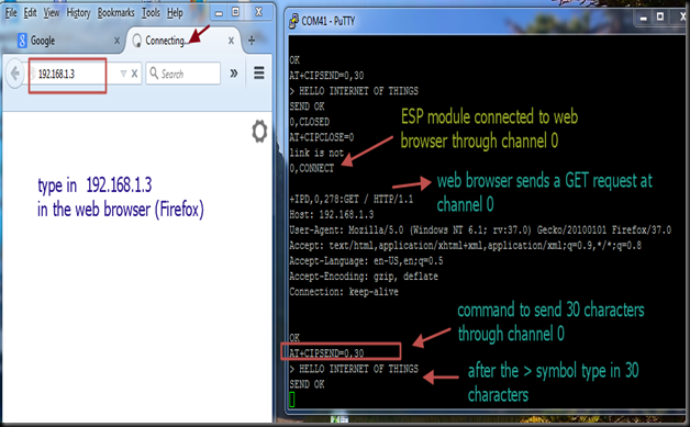
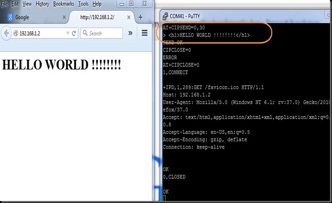
After you get OK  type in the command

AT+CIPSEND=0,30

This command is to send 30 characters through channel 0 .Use the channel number which is displayed as CONNECT while a request is received from the browser.

Image10

Now you get a  >  symbol , after which you’ve to type in 30 characters.

The module will wait till you type in 30 characters & finally displays SEND OK.

You’ve to type characters within the Timeout limit.Otherwise the link will be closed.

Image11

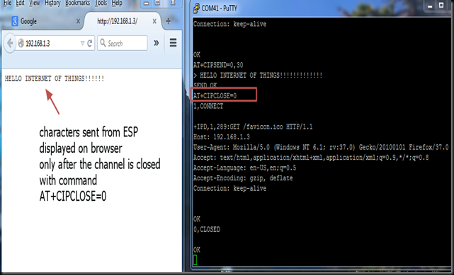
Now the characters are sent to the Web browser.

But the browser is still waiting for the channel to be closed.

Type in AT+CIPCLOSE=0

Here use the channel number ( 0) where the connection was established .

Image12

Once the channel is closed , you get the characters displayed on the browser.

HTML tags can be used to send characters

AT+CIPSEND=0,30

>

HELLO WORLD !!!!!
The above one displays characters using HTML tag type Heading 1.

Image 121

To close the server the command is AT+CIPSERVER=0 followed by a Reset AT+RST

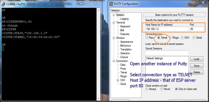
For testing 2 way communication , open another instance of PUTTY .

Select connection type as TELNET & Port 80.

Type in the host address , which you get by AT+CIFSR command in ESP window.

Click on open.

Image 122

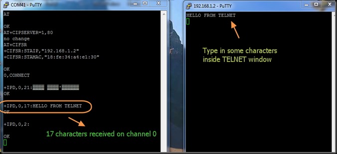
Type some characters inside TELNET window .You get these inside ESP window

+IPD,0,17:HELLO….

0 is the channel of communication & 17 is the number of characters received.

Image123

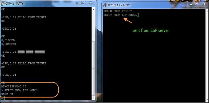
From within ESP window type AT+CIPSEND=0,20

ESP will wait till you type 20 characters.

On TELNET window the characters are received.

Image124

Watch this support video :

ESP WIFI Modules available at :

cooltext753793315  cooltext753790696

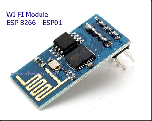
ESP8266 is an UART to WiFi module,  a really cheap and easy way to connect any small microcontroller platform (for example Arduino) wirelessly to Internet.

The ESP8266 is now one of the leading platforms for the Internet of Things. It’s super cheap, and super easy to work with.

This is a serial module with a built-in TCP/IP stack, so you can use it standalone

You can use AT commands to connect with WiFi networks and open TCP connections without need to have TCP/IP stack running in your own microcontroller: You can simply connect any microcontroller to ESP module and start pushing data up to internet.

esp1

There are several module designs called ESP-x where x is 1 to 12, so far.

I am using the ESP-1 module. The new firmware  is set at 9600 baud. provides the same 2×4 connector, Tx,Rx , RST, CH_DP(chip enable), and two GPIOs, GPIO0 and GPIO2.

ESP8266_pinout


ESP8266 is 3.3v device & cannot tolerate 5v levels.

Make sure you pullup the CH_DP and the RST line. I used  3k3 resistor to pull up  RST to +Vcc.

CH_PD is directly connected to +3.3v .Unless you connect CH_PD to Vcc , you won’t get any response from the module. The firmware boots up only on this connection.

So far it seems you can leave the GPIOs floating. For upgrading the firmware , however , the GPIO0 must be grounded.

The current consumption of the module is  80mA at idle state &  it can draw as much as 300mA during operation.

  1. Vcc: 3.3V, up to 300 mA
  2. GND: Ground
  3. Tx: UART Tx of the module, to be connected to the  Rx of the microcontroller
  4. Rx: UART Rx of the module, to be connected to the  Tx of the microcontroller
  5. RST: Reset/Restart, pull to GND to restart
  6. CH_PD: Chip enable, used for flash boot .
  7. GPIO0: pulled low for update mode
  8. GPIO2: not sure yet???

setup1


I used a USB to TTL converter for connectivity between PC & WIFI module.The converter has 3.3v output which is used to power the WiFi module. It has also a +5v supply out.

Care has to be taken with power supply as the unit is to be powered at 3.3V and using 5V will probably kill it.

For ease of connections I’ve used a Breadboard.The connection details are as below :

WIFI Module       USB-TTL

Vcc     —  3.3v

Gnd      — Gnd

Tx        — Rx

Rx        — Tx

CH_PD   — connected to 3.3v to enable chip firmware boot.

RST        —  connected to 3.3v through 3k3 resistor

CH_PD pin acts as an enable signal, without it the board is mute and deaf. If CH_PD is not pulled HIGH , you won’t get any response from the module.

Once you connect this last pin to VCC (remember 3.3V) the module is brought to life, and after some garbage in the serial port you can read the word “ready”. Once you get there things will start to get interesting.

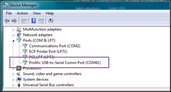
The USB-TTL converter I used required a driver “Prolific 2303” to be installed.After installing the driver , I got the port allotment under device manager while the converter is connected to a USB port of PC.

Image 1

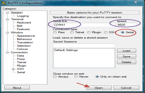
A serial Terminal software PuTty  is used to communicate with the port where USB-TTL converter is connected.

Open PuTty & select Serial .Feed in the port number seen under Device manager (here it’s COM41) & speed as 9600 (Baud Rate).


Image 2

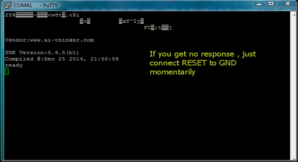
Click on OPEN button to see the Terminal black window.

Try to type in AT .If you do not get any response , just momentarily connect the RST pin of module with GND.

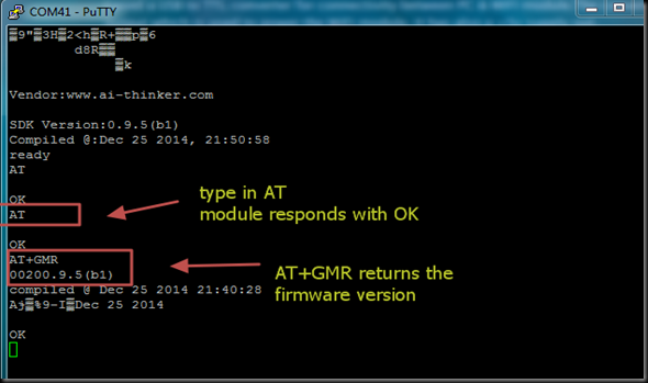
You get some garbage data initially & then the address of the vendor “www.ai-thinker.com”

followed by the firmware version & then “ready”


Image 3


Now type in AT .The module will respond with OK. If not ,close the Putty window & again open it & proceed with above steps.

AT+GMR will return the current firmware version.


Image 4


Generally , you can inquire the module with AT command followed by question mark ?

or you can assign a value  , by using equal to = , after the AT command.

All AT commands must end with a “\r\n” – a carriage return & a New Line.

For detailed list of AT commands visit :

http://room-15.github.io/blog/2015/03/26/esp8266-at-command-reference/


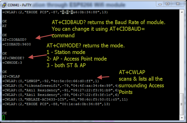
AT+CIOBAUD? will return the Baud Rate the module is working with.

AT+CWMODE? returns the Mode of operation of the module.

CWMODE returns an integer designating the mode of operation either 1, 2, or 3.
1 = Station mode (client)
2 = AP mode (host)
3 = AP + Station mode (Yes, ESP8266 has a dual mode!)


Image 5


But the magic starts once you try AT+CWLAP command, that will provide you a list of available wifi access points in the area.

The command AT+CWLAP will list access points in range. This was very encouraging, not only is my access point (MBLAZE..) on the list, but the ESP can see at least as many access points as my laptop can .

The APs are listed as  +CWLAP: ecn,ssid,rssi,mac

The Parameter are

ecn:  0 OPEN  , 1 WEP , 2 WPA_PSK , 3 WPA2_PSK , 4 WPA_WPA2_PSK
ssid: string, SSID of Access Point
rssi: signal strength
mac: string, MAC address

In the above screen shot you can see my AP “MBLAZE..” is WPA2_PSK  (3) password protected.You can see some other APs which are open  & not protected with password .They are listed with ecn 0.


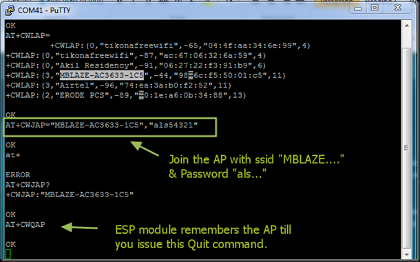
Next you want the board to join a certain access point (most of us want the board to act as a STA or WIFI client that will connect to an access point). That behavior is selected with the AT+CWMODE=1. You will need to reset your board after making this selection.

To connect to your home/office access point you issue the command AT+CWJAP=”yourSSID”,”yourWifiPassword”

The good news is that from now, every time you power the board it will try to connect to the same wifi network. You can see if it was successful by checking your router’s DHCP client list.

Even if the power is removed , the ESP module will remember the joined AP .

You can make it forget by issuing the QUIT command AT+CWQAP


Image 6


Alternatively you can check your module IP address with command AT+CIFSR. Once you know your board’s IP address you can try pinging it from your computer.

In the upcoming posts we shall investigate the module in TCP client and server modes.


For availability of these modules contact :

cooltext753793315   cooltext753790696

It is quite simple to pair a Bluetooth module from your Android phone.But bit tricky to pair it with another HC-05 module.In this post I’ll describe the method of pairing 2 BT modules.One of the module is assigned ROLE as MASTER  & the other left as SLAVE.

By default all HC05 modules are SLAVEs.Using AT commands the module can be configured as we like.

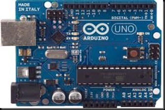
To configure the SLAVE we make use of an Arduino UNO board.Not much of configuration needed for slave.We can leave it to defaults.But to know the ADDRESS of the slave you’ve to follow this procedure.

ARD

Before connecting the HC05 module , upload an empty sketch to Arduino. This bypasses the Boot loader of UNO & the Arduino is used as USB-UART converter.

void setup() {}

void loop() {}

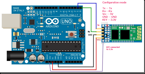
After uploading this empty sketch,remove USB power from Arduino & do the following connections with HC05 Slave :

——————————————-

ARDUINO        HC05

Rx(pin0 )  —>     Rx                Remember it is one to one connection here & not cross connection

Tx (pin1) —->    Tx

+5v     ——-> VCC

GND     ——-> GND

+3.3V  ——–> KEY

————————————————-

Now provide the USB cable power to Arduino.The HC05 module enters the Command mode with Baud Rate 38400.

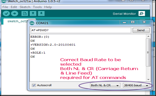
Open the Serial Monitor of Arduino .

Ensure to select “BOTH NL & CR”  & Baud Rate as 38400 at the bottom of the serial monitor.This is very important as the Bluetooth module HC05 expects both Carriage Return and Line Feed after every AT command.


AT_SLAVE

If you type in AT & click on SEND button you should get an OK confirmation from the HC05 module.

If you get ERROR(0) try again to enter the Command mode.If there is no response then check whether correct COM port has been assigned in Arduino IDE & confirm Baud Rate is 38400 , “Both NL & CR” selected.

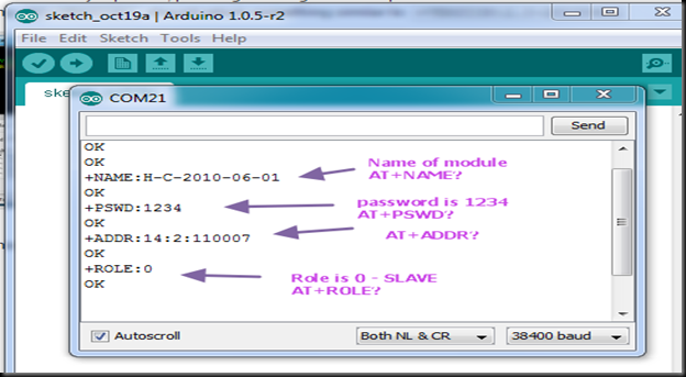
Type in AT+NAME?    to get the name of the module.You can change the name as you like with

AT+NAME=HC05_SLAVE

The password by default is  1234 .Confirm that with AT+PSWD?

The ROLE of the module can be known by typing  AT+ROLE?

You can change it by AT+ROLE=0    0 for SLAVE & 1 for Master. Leave it as 0 as we want this module to be SLAVE.

You should know the Address of this module to make it PAIR with another.Type in

AT+ADDR?

& note the Address.Here it is  14:2:110007.

While using this address in AT commands you should replace the colon with a comma , like

14,2,110007

Now remove the KEY connection from the HC05 module & disconnect the power.

Again provide the power to see STATUS LED on the module blinking fast indicating that it is looking for a PAIR.

MASTER Module setup

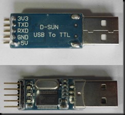
To configure another module as MASTER a simple USB to TTL converter is used.


hc05_1             usb-ttl

Following are the connections between HC05 & USB-TTL module.

————————————————

HC-05          USB-TTL

VCC    —–>   +5V

GND   —–>   GND

Tx      ——>   Rx        Note the CROSS connection here

Rx      ——>  Tx

KEY     ——> +3.3V

————————————————-

We make use of a Terminal Software TERATERM to configure the MASTER.The advantages of this Terminal software are

– It supports CR+LF Carriage Return and Line FEED after each command , which is a must for HC05

– Sends command with zero Transmit delay , as the HC05 module interprets commands immediately.

You can download TERATERM  here

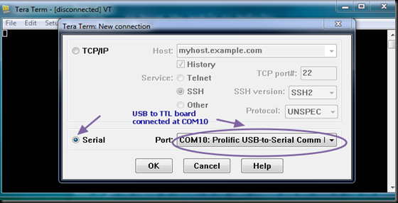
Open the TERATERM terminal & select SERIAL & the port number where the USB-TTL module is connected.

TERA1


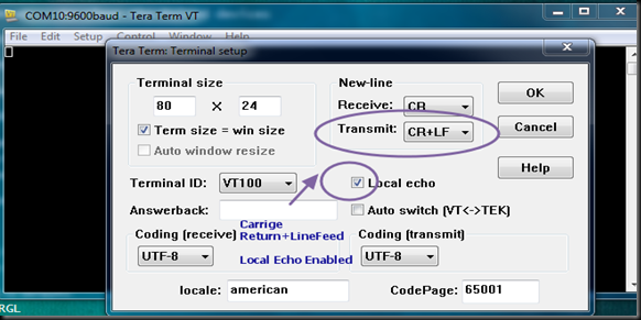
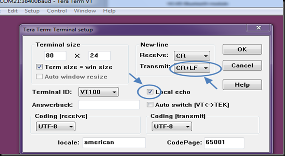
Under SETUP –> Terminal select CR+LF for TRANSMIT


TERA2


Also check mark “Local Echo “ so that you see what you type.

tera3


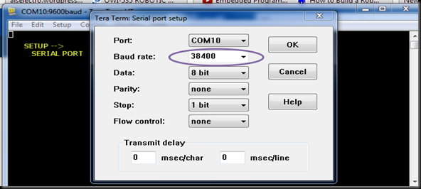
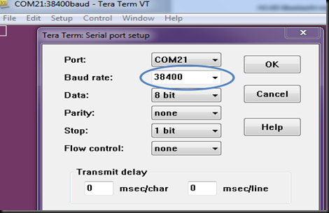
Under SETUP –> SERIAL PORT select the Baud Rate as 38400 , 8N1

TERA4.1

If you type in AT you should get an OK response.

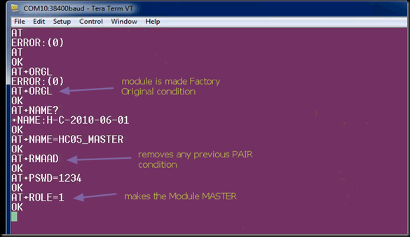
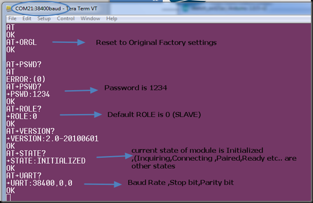
Reset the module by issuing AT+ORGL  which restores the module to original state.

You can change the name to user friendly one by typing AT+NAME=usergivenname

AT+RMAAD  will release the module from any previous PAIR.

AT+PSWD=1234  to set the password as 1234

AT+ROLE=1  changes the ROLE of the module to MASTER


tera5

AT+CMODE=1

Allows connecting to any address.

Default is CMODE = 0 which allows connection to only bound address.

Start SPP profile library (needed to do any Bluetooth transmitting/receiving):

Serial Port Profile (SPP)

While Bluetooth specifications define how the technology works, profiles define how it’s used.

If you’re replacing a serial communication with Bluetooth, SPP is the profile for you. SPP is great for sending bursts of data between two devices. It’s is one of the more fundamental Bluetooth profiles.

Using SPP, each connected device can send and receive data just as if there were RX and TX lines connected between them.

Initialize the SPP Profile library by typing

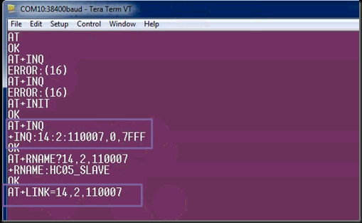
AT+INIT  

If you get ERROR(17) , it means you’ve already issued this command & you can continue ignoring the error.

Start searching:inquire surrounding bluetooth devices

AT+INQ

A short list of devices found should appear, one of them will be the slave module.

The format of the output is as follows:
+INQ:address,type,signal   e.g.  14:2:110007,0,7FFF

Type can be ignored. The signal will be 7FFF since inquire is in standard mode.

Copy the address part of the devices found, for example 14:2:110007 and change the colons to commas – 14,2,110007.

To find out which device is the slave module you will need to query each address for its name:
AT+RNAME? <address>

Replace <address> with address of device like 14,2,110007

Response should be +RNAME:HC05_SLAVE if you’re using a master module as a slave.


And now to actually connect to the SLAVE

AT+LINK=<address>

AT+LINK=14,2,110007

tera6

You can watch the status LEDs of both slave & master.The fast blinking Status LED  starts flickering slowly & the Pairing LED goes steady.

Now you can remove the KEY connection from master & Reset the module by removing the power & connecting back.

On powering back the MASTER ,the Slave gets paired with it automatically which can be verified by the LEDs on board.The paired devices are remembered even after disconnecting power.

Now these two modules can replace the physical serial connection of your project.

Bluetooth networks (commonly referred to as piconets) use a master/slave model to control when and where devices can send data. In this model, a single master device can be connected to up to seven different slave devices. Any slave device in the piconet can only be connected to a single master.

The master coordinates communication throughout the piconet. It can send data to any of its slaves and request data from them as well. Slaves are only allowed to transmit to and receive from their master. They can’t talk to other slaves in the piconet.Maximum 7 devices are allowed in this piconet network.

Watch this support video :

Pairing HC-05 BLUETOOTH Modules


NEW UPDATED VIDEO with code examples :

cooltext753793315     cooltext753790696

The Bluetooth module HC-05 is a MASTER/SLAVE module.The Role of the module (Master or Slave) can be configured only by AT COMMANDS.

By default the factory setting is SLAVE.

This post walks you through the AT commands of Bluetooth module .Through AT Commands you can change the ROLE of the module. Name,Password of the Module can be changed .The list of AT commands can be downloaded HERE 

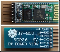
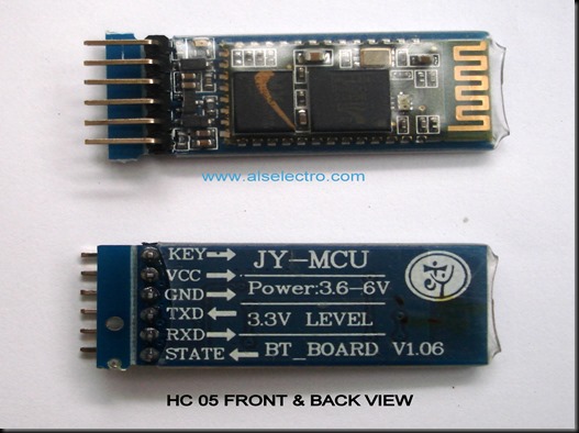
Remember the models HC-04 or HC-06 are SLAVE only modules .HC-05 is the module of interest in this post.To identify the model you can see the pin count.If the module has 5 or 6 pins it is HC-05.If the module has only 4 pins then it is HC-04 or HC-06.

The firmware for HC04 is LINVOR & for the HC05 it is HC05 itself.If you scan for bluetooth devices from your Android phone you can see this name.

The extra pins in HC-05 are the KEY & STATE pins.The KEY pin is used to enter the Command mode.


     hc-05_2                         hc-04

HC05 Pin count is 6    MASTER/SLAVE             HC-04 Pins 4  SLAVE ONLY

The slave modules can not initiate a connection to another Bluetooth device, but can accept connections.Master  module can initiate a connection to other devices. Be sure not to make the mistake of buying 2 slaves (HC-04) .

To enter the Command mode you can either use an USB TO TTL Module or your Arduino UNO board.

usb-ttl     OR     arduino

       USB TO TTL DEVICE                            ARDUINO UNO

First let me explain how to use the Arduino board for the configuration.We need to use the USB – UART portion of the Arduino board bypassing the bootloader function of ATMEGA328.For this connect the Arduino to PC & just upload an empty sketch

————————–

void setup()

{

}

void loop()

{

}

————————–

Connect    Rx (pin 0) of Arduino to  Rx of Bluetooth module.

                 Tx (pin1) of Arduino to Tx of Bluetooth module.

Yes,I’m correct.The connection is one to one while using Arduino as USB-UART board.It is not the other way (Tx  to Rx while using USB-TTL board).

Before connecting the power to HC05 module  you should know that there are there are two ways of activating command mode on these devices.

One is to hold pin 34 high (KEY) as the device is powered on and it should enter command mode at 38400,8,N,1

The other is to hold pin 34 low then set it high after the module has been powered on and it will enter command mode at the pre-programmed speed (default is 9600,8,N,1).

Let us complete all the connections and finally provide power to the module.

  HC-05      ARDUINO

           Tx –—>  Tx (1)

           Rx –—>  Rx (0)

           Vcc ––> 5v 

           GND –-–> GND,

           KEY –—> 3.3V

   Now provide the power to the module by connecting USB cable to Arduino

The Status LED starts blinking slowly (once per 2 secs).This indicates that the module has entered the command mode at the BAUD RATE 38400.

You can use the SERIAL Monitor of the Arduino to feed AT commands.

At the bottom of the SERIAL monitor ensure that you select  “BOTH NL & CR” .This will feed /r/n   after each command.Generally while using Arduino ,the println() statement), appends both carriage return and newline .(In case of PIC or 8051  you should add terminator ( “0x0d 0x0a”) to the program.)

HC 05 module needs a CARRIAGE RETURN & LINE FEED after each command .

Now open the Serial monitor of Arduino with settings BOTH NL & CR , Baud Rate 38400

Type in AT  & click on Send.

You should get a OK response from the module.


1_ard           

The default ROLE of HC-05 is SLAVE .To change this to MASTER type in

AT+ROLE = 1

The module responds with OK.

To confirm , type in AT+ROLE ?

The module will reply the status as ROLE 1.

You can also use a Terminal software like TERATERM to feed the AT Commands.

Close the Serial monitor of Arduino & then start the TERATERM terminal.

Select Serial at the start up window of TERATERM.

Under SETUP –> Terminal  select CR+LF of Transmit & tick mark the LOCAL ECHO (to see what you type)

3_ard


Under SETUP –> SERIAL PORT select the BAUDRATE 38400 , 8N1

4_ard

Now you are ready to feed the AT commands.

2_ard

To query a condition like Name, Password ,etc. you need to use a question mark after the command.

To change the condition use the equal to mark = after the command.

For e.g to query about password you type in  AT+PSWD? 

To change the password you type in AT+PSWD=1234

In the next post we shall see how to pair 2 nos. HC-05 modules so that it can replace the physical Serial connection.This can be an alternative to ZIGBEE , but with less range and more data speed (2Mbps).

BLUETOOTH Module

The easiest & economical way to go wireless in an Embedded project is through a Bluetooth module.Your Serial communication goes Wireless using this module.

The types available in the market are HC-04 , HC 05 &  HC06 .The HC 05 is a Master/Slave module & the other two models are Slave only models.The Slave only models need a Master like Android phone to get paired.

HC05 model can be configured either for a Master or for a Slave mode , thus most preferred for a Microcontroller project.

The HC-05 module can build a connection to other modules, while HC04/HC-06 modules can be a slave only.Two Slave modules  cannot communicate with each other themselves.

HC04 is factory loaded with LINVOR firmware.If you power up the module and scan for Bluetooth devices using your Android phone , you can see the name LINVOR on the phone.If the module is HC05 , you see the name HC05 on the phone.

The square wave like design on the top of module acts as antenna &  the range is about 30 feet.

The specifications of different models of Bluetooth module is on this Wiki page :

http://wiki.pinguino.cc/index.php/SPP_Bluetooth_Modules

bt_raw

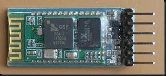
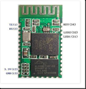
Above is the picture of a raw HC05 Bluetooth module .The module operates on 3.3 V DC power & the acceptable TX/RX signal level  is 3.3v & not 5v. The KEY pin (pin 34) on a HC05 module plays an important role in entering AT mode of the module.

I suggest to buy a module on a breakout board and available as JY-MCU modules.The Bluetooth module is mounted on a breakout board and connections provided using header pins.You can safely provide 5v power to this board, as it has an inbuilt 3.3v regulator.Also the board has Status LEDs for visual indication of status of module.

DSC00001

The module is covered with a plastic transparent sleeve.If you need to access all the pins , cut this sleeve out.Mostly the header pin connections extended is enough for connection to a microcontroller.

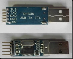
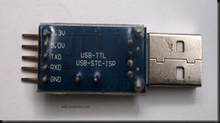
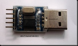
To connect this module to a Laptop  an USB to TTL converter board built on Prolific’s 2303 IC is required.

This is an inexpensive module with USB at front & header pins for connections.When connected to PC you need to install the driver for Prolific 2303.

http://www.prolific.com.tw/UserFiles/files/PL2303_Prolific_DriverInstaller_v1_9_0.zip

DSC00002     DSC00003

The connections between HC05 module & the USB converter are simple as below :

HC – 05 MODULE      USB-TTL MODULE

VCC       ——>         5.0V

GND       ——>        GND

TXD       ——>         RXD

RXD     ——>          TXD

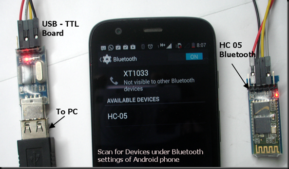
Now plug the USB connector to a port on your PC.The power LED on USB board glows & the Status LED on Bluetooth board starts blinking fast , indicating that it looks for a pair.

From your Android phone , go to Settings , switch ON the Bluetooth & under properties Scan for available Devices.

The Bluetooth module will show up as HC-05 under Available Devices.

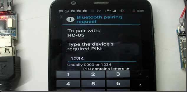
bt6

Touch on the HC-05 & feed the PIN password as 1234.

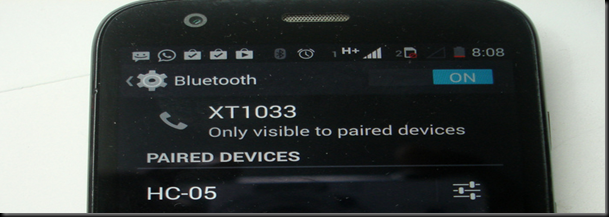
bt7

Touch OK to see the HC-05 under paired Devices.

bt7

To communicate with PC you need Terminal software on Android phone as well as on the PC.

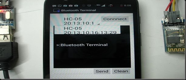
From Android’s Market search for “BLUETOOTH TERMINAL”. Select the one with Bluetooth symbol  and install it.

image

Open the installed Bluetooth terminal.On the top you can see a Connect button & to its left bottom a small drop down arrow is seen.Touch that drop down to see the available devices.

Touch on the HC-05 & then Connect

bt8

Now the fast blinking of LED on HC05 SLOWS DOWN TO ONE BLINK per second indicating that it has been paired with a Master ( Android phone).

Now we’ve to install a Terminal software  like Putty or CoolTerm on your PC.

PuTty download link : http://the.earth.li/~sgtatham/putty/latest/x86/putty.zip

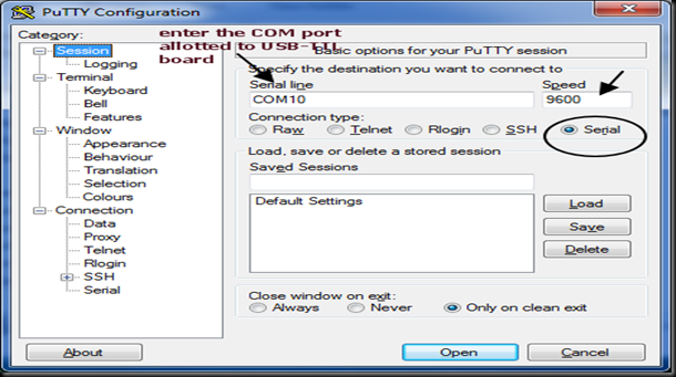
Open Putty & under Session select Serial.Enter the COM port allotted to the USB-TTL board (here it is COM 10).This can be noted down from the Device Manager’s COM port allocation.

Enter the Speed as 9600 which is the Baud Rate of communication.

putty1

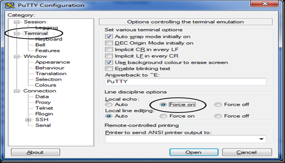
Under Terminal Settings ensure that Local Echo – Force ON is selected.This enables you to see what you type on Putty screen.

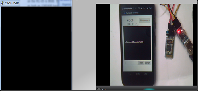
Click on Open to see the Terminal window for communication.

putty2

If the connection is lost Touch Connect again on the phone.

putty3

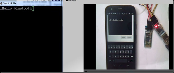
Type in some characters on the Phone & touch SEND.

You can receive the characters on the Putty screen.

putty4

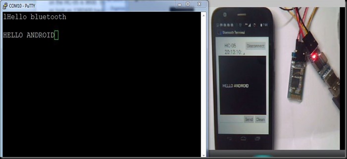
Same way type in some characters inside Putty screen to see them received on the phone.Thus a 2 way communication is established.

putty5

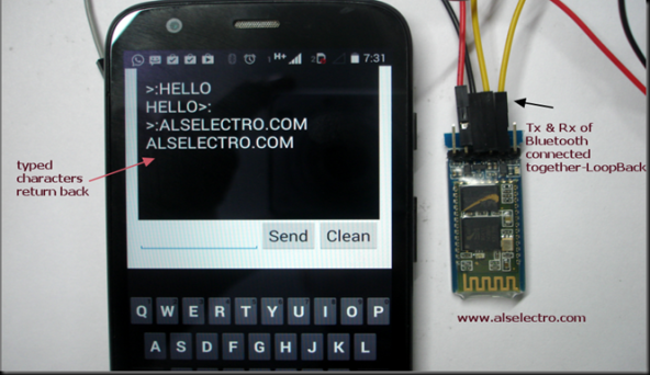
You can also test a Loopback method.

Connect the Tx & Rx of Bluetooth module together .For this test PC 7 USB board are not required.Just you need to provide 5v power to module & loop the Tx/Rx.

Now the characters sent will be received back.

putty7

Watch this support video :

http://www.dailymotion.com/video/x21srh5_bluetooth-module_tech


BLUETOOTH MODULES

cooltext753793315