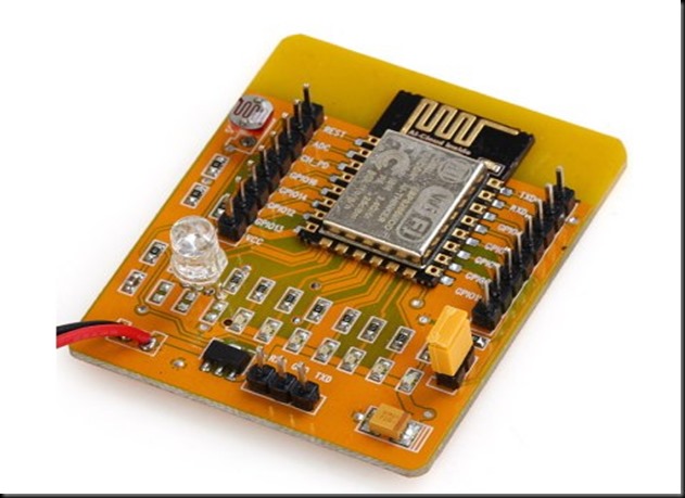
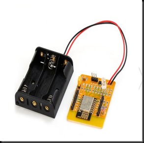
Link to previous posts 1.AT Commands , 2. TCP Client/Server , 3. Connect to Android
In the previous posts we’ve tested the WIFI module in TCP Server/Client mode & how to control from an Android mobile.These are related to LAN – Local Area Network where the WIFI module & Mobile are connected to the same ACCESS POINT (AP).
The AP I’ve used is a WIFI Dongle MTS MBLAZE. For the outside world to contact the ESP module connected to MTS , PORT FORWARDING should be done. This is a method by which the IP address of ESP module is forwarded , so that any one accessing the particular port of external IP will land on the ESP module.
The problem is WIFI Dongles do not allow Port Forwarding . As I’ve previous experience in CCTV DVR port forwarding (you can watch my video on DVR port forwarding Here ) using land line Internet connection , I decided to apply the same technique for ESP WIFI.
No Internet Dongle allows port forwarding. TPLINK MR3420 Wireless 3G/4G Router came to my rescue.
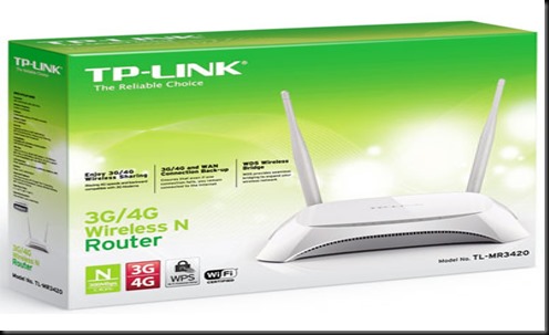
Following are the tasks we need to do :
1.Configure TPLINK ROUTER to accept 3G Internet Dongle
2.Connect ESP to TPLINK on WIFI & Start a SERVER on port 333
3.PORT FORWARDING ESP’s IP on TPLINK ROUTER CONFIGURATION
4.WINDOWS FIREWALL SETTINGS
5 :Know your External IP & Port Open Condition
6.Connecting from a Distant PC anywhere in the World
STEP 1.CONFIGURE TPLINK TO ACCEPT 3G DONGLE
The TPLINK Router accepts USB Dongle as well as WAN connection.I plugged in my MTS dongle to the USB port of TPLINK.
One of the Ethernet ports is connected to the PC using RJ45 cable.
To configure the Router , open the browser & type in the Address of the Router .The IP address is 192.168.0.1
Both user name & password is admin
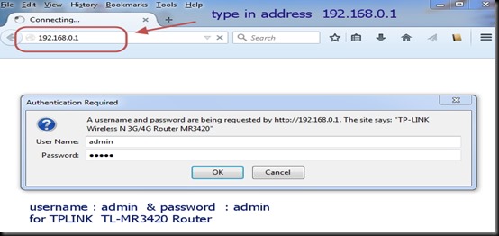
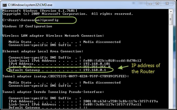
To know the Routers IP , you can type in CMD to open Command window .
After the prompt type the command “ipconfig” .The Default Gateway address is the IP of Router.
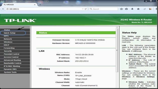
The configuration window of Router appears.
Select “QUICK SETUP”
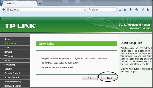
Click Next button.
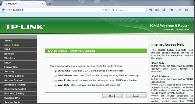
Select Internet access mode as “3G/4G ONLY”.
Select your Mobile ISP from the drop down menu .Mine is MTS .
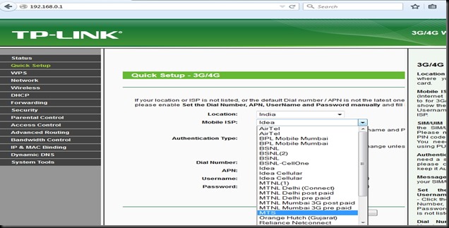
Rest of the settings you can leave it for defaults.

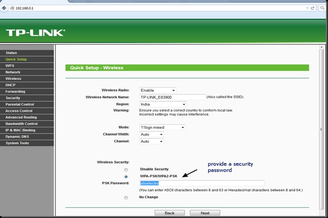
Click NEXT & under Wireless Security select WPA2_PSK mode & provide a password.
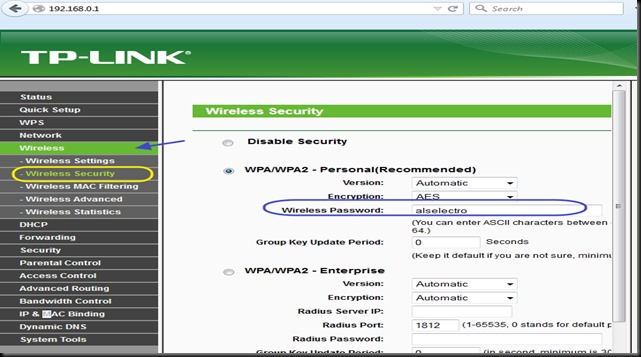
Click Next & then FINISH to complete the quick setup.
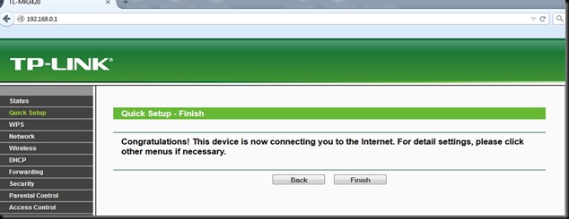
Under Status you can see the 3G/4G USB Modem as Identified Successfully
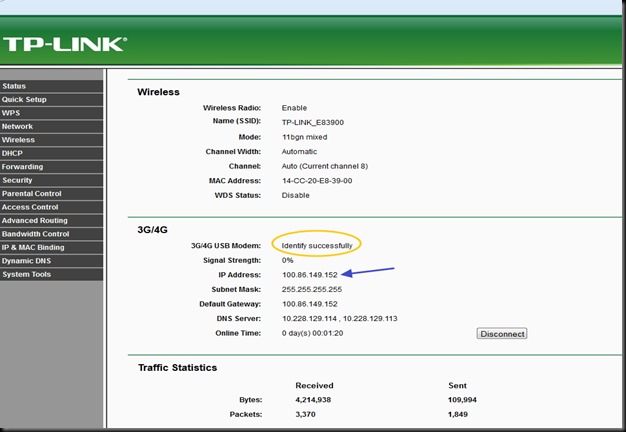
For now the TPLINK Configuration is completed.We shall connect the ESP WIFI to TPLINK Access Point , Start a Server on ESP Module & again come back to TPLINK to configure PORT FORWARDING.
STEP 2 : Connect ESP to TPLINK on WIFI & Start a SERVER on port 333
We make use of Putty Terminal software to communicate with ESP module.
You can download PuTty here.
Open Putty & select Serial .Feed in the COM port where ESP is connected (through USB –TTL board) & select the Baud rate as 9600.
Now if you type in AT , you get OK response.
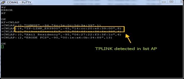
From the Putty window ,search for the surrounding Access Points (AP) using the command
AT+CWLAP
You can see the TP-LINK under listed APs.
Join TPLINK AP using the password we’ve setup already with the Router.
AT+CWJAP=”TP-LINK_E83900”,”alselectro”
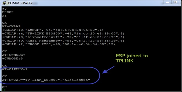
For allowing multiple connections
AT+CIPMUX=1
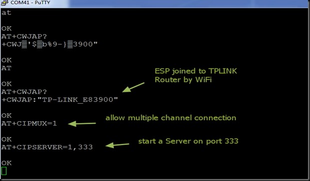
Now start a SERVER using command AT+CIPSERVER
You can use any port no. within 65536 , except the standard allotted ports like HTTP (port 80), FTP (21) , Telnet (23) , etc.,
The default server port for ESP is 333.Let us start a Server on that port using command :
AT+CIPSERVER=1,333
To know the Station IP type in
AT+CIFSR
This returns the Access Point IP & the Station IP.
If CWMODE =1 , you get only the STAIP. Default is CWMODE=3 , which gives both IPs.
The STATION IP here is 192.168.0.100

This Station IP is an Internal IP & cannot be contacted from outside world.To enable contact this IP , we need to PORT FORWARD .
As we’ve started a Server on port 333 , we shall forward any contact on this port to the Station IP.
STEP 3 : PORT FORWARDING ESP’s IP on TPLINK ROUTER CONFIGURATION
Open the TPLINK configure window which we’ve opened initially, by typing in 192.168.0.1 (IP of TPLINK Router ) , username & password both are – admin
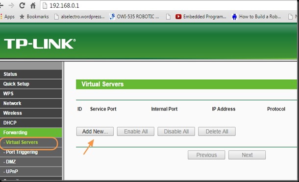
Under FORWARDING select VIRTUAL SERVERS
Click on ADD NEW..
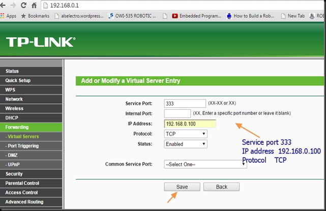
Enter the Service port as 333 , as we’ve started a server on this port on ESP.
Fill in IP address as 192.168.0.100 , which is the Station IP of ESP.
Select Protocol as TCP & Status Enabled.
Click on SAVE . The Internal port will be assigned same as Service port automatically.
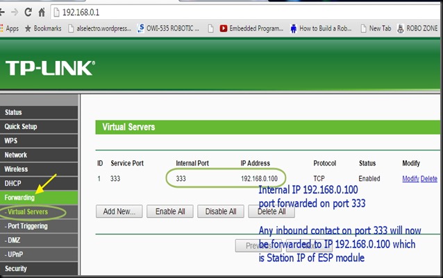
Now we need to allow this port for incoming traffic on the Windows Firewall settings.
STEP 4: WINDOWS FIREWALL SETTINGS :
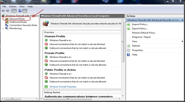
Type in FIREWALL on Windows search bar & select “Windows Firewall with Advanced Security “
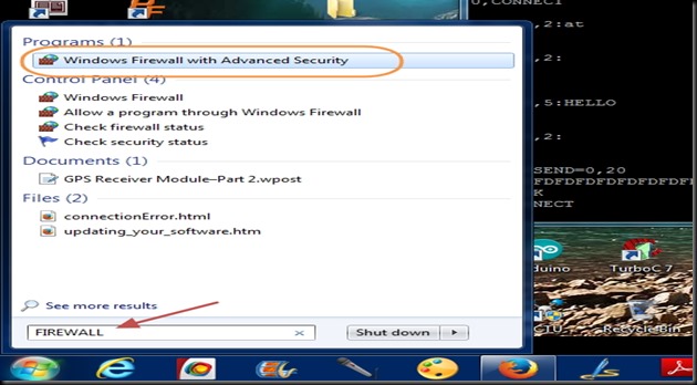
Select “INBOUND RULES “ on the left pane.
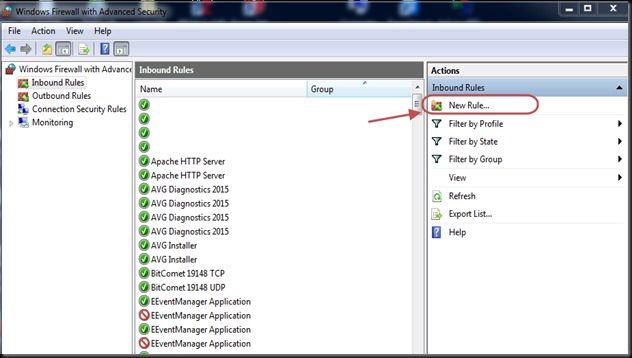
Click on “NEW RULES” on the right Actions pane
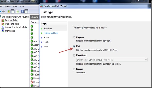
Select PORT as Rule type on the next screen.
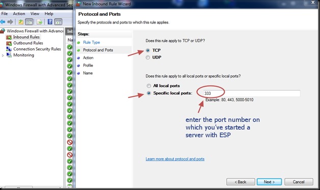
Select Protocol as TCP & enter the port number 333 under Specific Local Ports.
Select “Allow the Connection “.

Apply rule to all Domain,Private & Public.
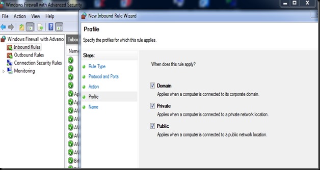
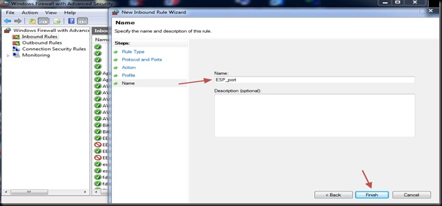
You can name the rule & click Finish to save it.
STEP 5 :Know your External IP & Port Open Condition
The Router is accessed from outside world by its external IP. This external IP is assigned by the ISP provider.Generally this IP is DYNAMIC ,which means every time you switch on your Router , a different IP is assigned.
For a fixed IP , you’ve to contact your ISP provider & pay for a STATIC IP.
Open your web browser & Google for “ what is my ip “
Your public IP address will be displayed.Note that down.
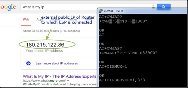
Now we shall check whether the port 333 is open or not.
Visit the site www.canyouseeme.org
Your IP will be automatically displayed.Under “ Port to Check “ enter the port number 333
& click on CHECK PORT.
You see SUCCESS message only on following conditions :
1. Router TPLINK Port Forwarding setting is done so that incoming request on port 333 is forwarded to the Station IP of ESP.
2. Windows Firewall setting Inbound Rule is set to allow communication on port 333.
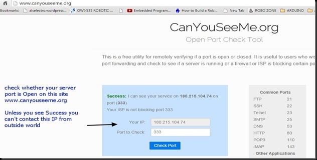
Only on getting SUCCESS message under Canyouseeme.org you can proceed further.
Till now all settings & configurations are done on PC connected with TPLINK & ESP.
Next is the final step in which another PC is involved from anywhere in the world.
FINAL STEP 6 : Connecting from a Distant PC anywhere in the World
For demo purpose I’m using a separate PC with a different Internet connection.
You can see from screen shot below the IP address of the distant PC.
Open Putty window in that PC & select RAW as Connection type.
Feed in the External IP address to be contacted (that of ESP ) & enter the Port no. as 333
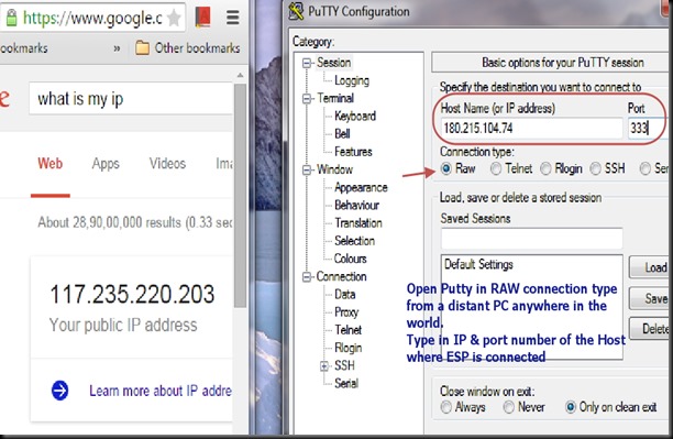
After entering the details , click on Load button.
Immediately you get response on the Putty window of ESP , like , +IPD,0,2:
From distant PC Putty window type in some characters .This will be received in the ESP window.
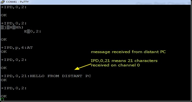
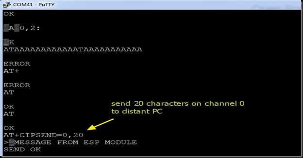
To send data from ESP , use command :
AT+CIPSEND=0,20
This command waits for you to type 20 characters to be sent on channel 0.
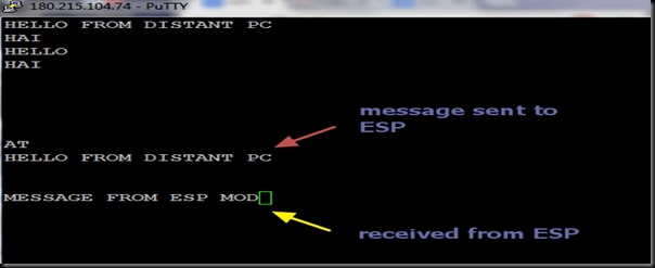
The following is the screen shot of Distant PC Putty window.
Note the IP address of distant PC on top of putty window.
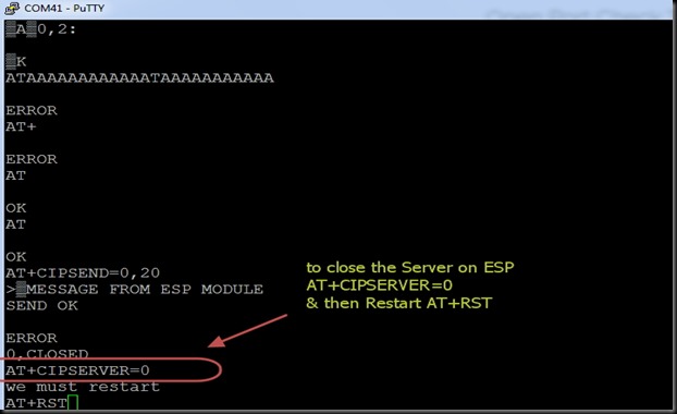
To close the Server on the ESP side , use command :
AT+CIPSERVER=0
& then Restart using AT+RST
Once you know the external public IP address of the Router & the Port number on which the server is started, you can contact this ESP from anywhere in the world !!!!


