Tag Archive: Port Forwarding


In the previous post PART 1  we explored the ways to make the local IP address of PC/ESP8266 STATIC.

In this part 2 we shall see how to make your Dynamic Public IP as STATIC using NO-IP account & then Port forward to the server started on port 350 of ESP.

PORT FORWARDING

First let us do the PORT FORWARD  settings.

For this , type in your Router’s Gateway IP in the browser & log in to Router’s Settings.Here my Router’s gateway is 192.168.1.1

The PORT Forwarding is done under VIRTUAL SERVER.

For different Router , you can check out this excellent link which guides settings for almost all types of Routers in the World.

https://portforward.com/router.htm

In my case the VIRTUAL SERVER is under ADVANCED —> NAT


image1

Under Virtual Server feed in the WAN & LAN ports as 350.

Under LAN IP feed in the static IP of our ESP8266.Here it is 192.168.1.10 which we made static as described in part 1.

Once the APPLY CHANGES button is clicked , the entry appears under Forwarding Table.

Image 2


WINDOWS FIREWALL SETTINGS


Next is the Windows firewall settings to allow communication through port 350.

Open Windows Firewall with Advanced Security.

Click on Inbound Rules & then New Rule.


Image 3


Select Rule Type as PORT.

protocol as TCP.


Image 4

Under Action select “Allow the Connection”

& tick mark all under the Profile.

Provide a Name for the Rule & save it.

Image 5


START SERVER ON ESP8266

Now open the Putty window where you’ve connected ESP8266 ( refer part 1 for details)

Before starting server , issue the command

AT+CIPMUX=1

Then start the server on port 350 using

AT+CIPSERVER=1,350

Image 111

Now the Server starts listening on PORT 350.


Convert Public IP to STATIC

The external world communicates with your ESP server using the Public IP of your Network.This IP is generally DYNAMIC which means it changes on every boot of your Router.

To make it STATIC we shall use a service called NO-IP which converts your public IP to a Domain name & follows the changes.

Visit www.noip.com

Sign up by providing your EMAIL.

Image 6

LOG IN  your NO-IP account.

Under Dynamic DNS click on ADD HOSTNAME.

Image 7

Enter the host name, for e.g , as   testmyiot  & from the dropdown select a domain , say, ddns.net.

Now your new host name is

testmyiot.ddns.net


Image 8

Next , click on Device Configuration Assistant.

Image 9


Under the dropdown select the host name we created , testmyiot.ddns.net


Image 10

Next step is to fill in the Device details.

Device type is SERVER

Device Brand is WEB SERVER

Router make – select your router name .If not found in list then select other

& then enter Router type as Home.

Image 12

On the Next window answer NO

We shall come back to this window shortly after setting the Router for NO-IP.

Image 13


On the next window , before clicking YES to log in device, go to the Router settings in browser where you typed in 192.168.1.1

Image 14


Click on SERVICE & then DDNS.

Most of the Routers support NO-IP & is listed on the drop down.

Select NO-IP

Image 15

Feed in the Host Name as testmyiot.ddns.net

Provide the email & password you used to create the NO-IP account.

Image 17

Click on ADD to save to DDNS Table of Router.

Now go back to your NO-IP account window.

Click YES to log in device.

Image 18

On next window click on TEST CONNECTION

Image 19

After a short time you should see SUCCESS.

Now you’re done with DDNS settings.You need not go further to Port forward tab, as we’ve already done it.

Image 20


Following is the procedure , in case your Router doesn’t support NO-IP .

If you do not see NO-IP under drop down of DDNS settings of Router,

go back to your NO-IP account & click YES to the question “Is there a computer always running on your Network?”.


Image 22


You’ll be taken to next window to download DUC.

DUC- Dynamic Update Client is a software which runs in the background of your PC to follow your public IP.

Download it & install.

Image 23

Before FINISH ensure to tick mark “Run DUC in the background”

Image 24

Now you’ll be asked to login your NO-IP account again

Image 25

Once you log in, the following windows appear.

Select the host name you created & click save.

Image 26

Now you can see all TICK marks in the DUC window.

DUC runs in the background & follows your public IP to the domain name you created.

Image 28


You can test the access to ESP server now from a distant PC.

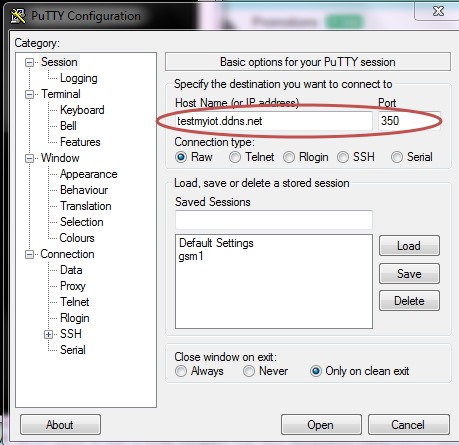
From anywhere in the world , make open a PUTTY window.

Select RAW & feed in the host name testmyiot.ddns.net & port as 350.

Image 29

You get CONNECTED to the ESP server


Watch this demo video :


cooltext753793315   cooltext753790696

This post is all about converting your device address in Network to STATIC & establish PORT FORWARDING.

For IOT projects it is easy to test in local setup using  the LAN IP starting with 192.x.x.x .But from outside world this IP cannot be reached.Here I will walk you through the steps to contact the local IP from outside world.This procedure is a major step needed in IOT projects  , without which external control is not possible.

Following is the setup of my Network. A ROUTER is on the top of the network for which the Internet Service Provider is Airtel . The Router is WIFI enabled so that I can connect multiple devices wirelessly.

Total 3 devices are connected to the Router as shown below.


setup_ok


On switching on the power , the Router (DHCP enabled) assigns local IP addresses to all the devices connected.The IP address assigned is DYNAMIC which means , it changes every time I switch on the Router.

There are two types of IP addresses: STATIC & DYNAMIC

STATIC addresses are just that – unchanging

Dynamic IP addresses are assigned on-the-fly & keeps on changing by every reboot.

Because most home users tend to turn their computers off, even broadband connections, such as DSL and cable, continue to use dynamic addresses. If your computer is off, you don’t need an IP address so someone else might get to use it.

Each time you connect to the internet, your ISP assigns you an IP address to use. This IP address is the Public IP which others use to communicate to your PC.This IP address is DYNAMIC which changes every time you newly connect to web.

The next time you connect, you might get a different address. If you’re only connecting out to the internet, that’s all you need.

If you expect people to connect in, say you want to run a web server that you want people to be able to find and visit, you’ll most likely need a STATIC IP address. A static IP is assigned by your ISP at an extra cost which is unnecessary for a home network.

In this post I shall explain the ways of changing the LOCAL IP address  as well as the PUBLIC IP address to STATTIC.Suppose you run a web server on your ESP or Raspberry PI & wish to connect from external world.It will work only for the first time , as you use Dynamic IP to communicate.

Next time you power up , the IP address might have changed.So using a STATIC IP is a must .


SETTING the Local IP of PC / Laptop to STATIC :


In my network the PC assigned a Dynamic IP of  192.168.1.10

Run –> CMD –> ipconfig /all       reveals the  address details as seen below :

ipconfig


Here you can see the Default Gateway is 192.168.1.1 which is the IP of the Router .To port forward settings we need to use this IP on a browser to enter the settings , which we will see later in the post.

Local IP assigned to the PC is the IPV4 address 192.168.1.10

Let us change this to STATIC now.

Open the CONTROL PANEL –> NETWORK and Internet  –> Network and Sharing center

Click on “Change adapter settings”

Image 10


Right Click on the Network connection & select Properties

Image 11


Select the Internet Protocol Version 4 & double click on it.

Image 12

Now you see the following screen where selection is done by default to obtain IP automatically.

Change this selection o “USE the following IP address “ & enter the IP as 192.168.1.150

The first three bytes must match that of the default gateway address which is 192.168.1.1

The last byte can be assigned at your will , within the IP range allowed by the router.

Here I change the IP to 192.168.1.150.  Note that only the last byte I’ve changed.

Subnet mask & Default gateway are entered as seen in the ipconfig /all window above.


Image 13


DNS server address also changed as seen in the screen shot below

Image 14

Image 15

Reboot your PC to see the changes effective.

Now the IP address of my PC will be 192.168.1.150 & remains STATIC even after reboot.

The above task can also be done automatically by a trial software :

PF_1


You can download the trial version here :

http://portforward.com/store/download-instructions/pfconfig/

The trial version allows all other tools except port forwarding.Open the tool & click on STATIC IP Address & follow the guidelines to fix your PC’s IP as STATIC.


STATIC IP for other devices ESP & Raspberry PI:


For making the Raspberry Pi’s Local IP to STATIC you can follow this blog :

https://www.modmypi.com/blog/tutorial-how-to-give-your-raspberry-pi-a-static-ip-address


Regarding the IP of ESP8266 we need not change anything.Once the STATION IP is assigned to ESP8266 , the module remembers the Access Point it has connected & the STA IP assigned .

or issue the command

AT+CIPSTA=”192.168.1.5”

Image 16

The ESP module remembers the Access Point it has joined with & the IP till you quit the AP.

But on Reset it seems to get changed.

The only way to assign STATIC IP to ESP module is through the Router settings.

In your browser type in the IP address of your Gateway , here it is 192.168.1.1

Under LAN setup look out for DHCP settings.

In latest Routers you see a setting called DHCP RESERVATIONS.

In the IP Address field, type the IP address to assign to the computer or server.
Choose an IP address from the router’s LAN subnet, such as 192.168.1.x.

Type the MAC address of the ESP MODULE server.
As the ESP has already joined the AP, it  is already on your network, you can copy its MAC address from the Attached Devices screen and paste it here.

Here I will show an example of setting the Static IP in DHCP Reservation under BEETEL Router

In almost all the Routers the settings are the same.Just look out for the wordings Open-mouthed smileHCP RESERVATION” or “DHCP STATIC “ under the LAN setup.


dhcp1


Under DHCP STATIC tab , enter the IP address you want to fix for the ESP module

dhcp2


Feed in the MAC ADDRESS of the ESP device.

dhcp3

You can learn the MAC address from the AT command AT+CIFSR of ESP module.

dhcp4

The MAC address to be entered without any special character like colon.Please check out your Router settings for entering the MAC address (generally given near the MAC address box , how to feed in the address).

dhcp5

Click on ADD to save the settings

dhcp6

Now RESET or power back the ESP module.

The IP address will be the same for ever.The Router will always assign the IP you’ve set for the ESP module.

dhcp7


In a  D-Link router, it is under  the setup.Go to Setup / Network settings / DHCP reservation. You can then ask the router to give a given MAC address a fixed IP address.
Alternatively, the ESP can request a certain IP address from the router which we’ve seen in the example of Beetel Router above.

Now that the STATIC IP is assigned, let us see the methods of PORT FORWARDING & converting your public IP to STATIC using NO-IP account in PART 2.

After struggling for nearly a week with MTS dongle , finally I found an excellent solution to enable PORT FORWARDING.

HUAWEI POWER FI  E8221 model dongle  is the solution I found.This dongle accepts any data SIM for internet connectivity & we can create a WIFI HOTSPOT with this dongle to connect max. of 10 devices.

Further it has got a VIRTUAL SERVER setting tab in the configuration , thus enabling Port forwarding.

There is no need of an external Router like TP-LINK (which I used with MTS , as seen in my previous post).

1

I’ve inserted a BSNL DATA SIM into the HUAWEI dongle for Internet connection.

The DEFAULT GATEWAY IP address while using Huawei is 192.168.8.1

This can also be found by opening CMD in Windows search bar & then typing the command IPCONFIG /ALL

Typing this Gateway address in the browser , you get the HUAWEI CONFIGURATION window.Here the service provider (for me BSNL ) name is displayed with connection status.

Image 1

Click on CONNECTION SETTINGS seen below the “Connected” status.

On left pane , under SECURITY tab select the VIRTUAL SERVER.

Before clicking the ADD button under VIRTUAL SERVER LIST , we’ve to configure the ESP module & start a SERVER on port 333.

Image 2

The ESP 8266 module is connected to PC through USB-TTL board & the COM port allotted in my PC is COM 48 .

I’m using PUTTY terminal software to communicate with this COM port.

Following is the screen shot on which you can see the AT commands used to connect ESP with HUAWEI on WIFI , & starting a server on port 333.

The selection of port is random.You can select any port within 65536 , except the standard ports like 80 (HTTP) ,  21 (FTP), 23 (TELNET) ,etc..

AT+CWLAP   – to list the surrounding Access Points near ESP module

AT+CWJAP=”ssid”,”password”   – to join the AP using the SSID name & its password.

AT+CIPMUX=1   — to enable Multiple connections before starting server

AT+CIPSERVER=1,333   –  to start a server on port 333

AT+CIFSR  –  displays the IP address . STAIP is the IP address we need to port forward.

Image 3

After starting the server on ESP8266 , we need to port forward under the HUAWEI configuration.

Click on the ADD button , seen under VIRTUAL SERVER LIST.

Fill in details as below :

Name  : ESP

WAN Port : 333

LAN IP   : 192.168.8.100

LAN Port  ; 333

Protocol : TCP

Status  : ON

Finally click on APPLY.

Image 4

Needless to say , you’ve to apply an INBOUND RULE on Windows Firewall settings to allow this port 333 . (check the previous post on how to do this).

The external world can contact this ESP only through the EXTERNAL IP address.To know the IP , just type in WHAT IS MY IP on Google .In my case it is 117.252.205.55

To confirm that the PORT 33 is open & listening , visit the online tool www.yougetsignal.com

You need to test this on the PC where you’ve connected the ESP module.

The external IP will be automatically displayed.You just  type in the port no. to verify.

Following screen shot shows that my port 333 is open

Image 6

Now we’re all set to contact ESP from outside World.

From a distant PC with different Internet connection , open a PUTTY terminal.

Select RAW as Connection type & type in the IP 117.252.205.55  & port no. as 333.

Following screen shot shows the PUTTY terminal which I’ve opened on a different PC with a different IP.

Image 5

On clicking OPEN button , the ESP Terminal at the other end will respond with

0,CONNECT

This means a connection established on channel 0.

Image 8

Now type in some characters on the distant PC terminal.

newip2

The ESP terminal responds with

+IPD,0,21:characters received

which indicates , it has received 21 characters on channel 0.

The screen shots with HUAWEI symbol (IP 117.252.205.55 ) is that of TERMINAL where ESP module is connected & the screen shot of distant PC is shown with the IP address 180.215.121.135

Image 9

To send characters from ESP , use the AT command :

AT+CIPSEND=0,15

This indicates that you want to send 15 characters on channel 0.

The ESP will respond with a > symbol & waits till you type 15 characters.

Image 10

The distant PC now receives the 15 characters you typed inside ESP terminal.

newip3

Hence a two communication is established with ESP Terminal & a PC from anywhere in the world.This opens the door for INTERNET OF THINGS where you can control the devices connected to ESP from anywhere in the World.

WATCH THIS VIDEO :

cooltext753793315    cooltext753790696

In the previous post we’ve seen the ways to control the ESP8266 WIFI module from anywhere in the world.The key to success depends on the PORT FORWARDING , where we route the contact on particular port to the local IP address of the WIFI module.

Nowadays USB dongles are used widely for internet access .This post will help you troubleshoot PORT FORWARDING.

Following is the SETUP diagram .

TPLINK ROUTER is on the top of the NETWORK. An MTS USB dongle is plugged to TPLINK Router (model TL-MR 3420 with 3G/4G support).

A Laptop is connected to TPLINK Router on Ethernet using RJ45 cable.

A USB to TTL board is connected to PC on which the ESP 8266 module is wired.

The ESP module is linked to TPLINK Router on WIFI using the AT Command AT+CWJAP=”SSID”,”password”


ip8

On switching ON the ROUTER , it assigns LOCAL IP address to the modules connected to it either on RJ45 (wired) or on WIFI.

In our set up the LAPTOP which is connected by wire is assigned 192.168.0.100

& the ESP module which is connected on WIFI is assigned 192.168.0.101.

Note that the allotment of address is on first come basis.When you power off & on the Router again , this allotment may vary.

You can RESERVE the address by selecting the DHCP tab of TPLINK configuration.Here select

Address Reservation & then feed in the MAC address of the devices you’ve connected to the Router.

To know the MAC address you can use the ADVANCED IP SCANNER TOOL.

Download & install the tool. Start the scanner to know the IP address & MAC address of the devices connected .

ip12

STEP 1:

Confirm that you’ve Internet access after plugging  the USB dongle to the TPLINK Router .You need to login the TPLINK configuration with address 192.168.0.1 & enter the QUICK SETUP for this process.

STEP 2 :

Start the SERVER on ESP module

ip2


STEP 3 :OPEN PORT SCANNER

To confirm that the port we’ve started server ( here port no. 333) is OPEN , we use a  port scanner tool .

Advanced Port Scanner is a small, fast, robust and easy-to-use port scanner for Win32 platform. It uses a multithread technique, so on fast machines you can scan ports very fast.

Also, it contains descriptions for common ports, and can perform scans on predefined port ranges.

Download it & install.

http://download.cnet.com/Advanced-Port-Scanner/3001-18508_4-98269.html?hlndr=1&part=dl-73294

Open Port scanner & under Select port range enter 100 to 500 . As we’ve to check port 333 , we enter the range below 500 .Click on SCAN .

IP4


The PORT SCANNER displays the result regarding status of PORTs of your PC as well as the module connected to PC.

Here we can confirm that port 333 is OPEN on IP 192.168.0.101 (ESP module).

 ip5


STEP 4 : SET UP FORWARDING RULE on TPLINK CONFIGURATION

On TPLINK configuration window , under FORWARDING select the tab VIRTUAL SERVERS.

Click on ADD NEW.. & enter the Service & Internal port as 333 .

IP Address as 192.168.0.101 , which is the local IP allotted by Router to ESP module.

Select Protocol as TCP & then SAVE the settings.


IP9


IP 10


STEP 5 : WINDOWS FIREWALL SETTINGS

Open Windows Firewall Advanced settings & click on INBOUND RULES.

SET the rule to allow communication on port 333.

IP11


Now you are set to check the condition of PORT 333 externally.

For this we make use of an online tool www.canyouseeme.org

On opening the site your external IP will be automatically displayed.Enter the port number to check.

Click on CHECK PORT.

ip 13

Unless you see SUCCESS on this test , you can’t contact your ESP module from external world.

If you get ERROR , open the TPLINK configuration & click on STATUS.

Note IP Address displayed under 3G/4G.

From another computer with a different internet connection try to PING this IP address.

Open CMD & type in PING x.x.x.x

ip1


If the PING result is OK , you can be sure that the ESP module can be contacted from outside world.

If the PING result is TIMED OUT , you can’t communicate with ESP.

The   STATUS tab in my case , as shown in above screen shot , indicates an IP address starting 100.86.x.x

Generally following IP address ranges are PRIVATE IP ADDRESS RANGES :

10.x.x.x

172.16.x.x

192.168.x.x

These are reserved by IANA for private Intranets & NOT ROUTABLE TO INTERNET.

Private addresses are not reachable on the Internet. Therefore, Internet traffic from a host that has a private address must either send its requests to an Application layer gateway (such as a proxy server), which has a valid public address, or have its private address translated into a valid public address by a network address translator (NAT) before it is sent on the Internet.

In my case , the MTS ISP provider hide the PUBLIC IP address.

The MTS dongle does not support VIRTUAL SERVER settings , which means PORT FORWARDING IS NOT POSSIBLE with MTS.

What I couldn’t understand was , while writing my previous blog ,it worked sometimes.While MTS customer support was contacted repeatedly , they finally accepted that port forwarding is blocked by them.

After sleepless nights I’ve found a solution….. Read on my next post ….


cooltext753793315    cooltext753790696