Tag Archive: Universal programmer


First time in India , VEGA ROBOKITS has engineered a development board universal to both AVR & 8051 ICs.The board has in built Programmer capable of programming both AVR & 8051 family ICs.


board2


A 40 pin ZIF socket is used as Target to hold the 8051 IC. Additional 40 pin ZIF socket with modified connection is provided to host AVR ICs.This additional ZIF socket should be placed over the on- board ZIF socket to use AVR ICs.


image4


board1


8051 PROGRAMMER & DEVELOPMENT

To start with we shall see how to use this board for 8051 development.

Select switch 1 to USB position ,if you connect the board to PC using A to B USB cable.Now the power is taken from USB itself. If this switch is selected to other side , the board needs an external 12v/1A adapter.

Select the ISP switch (switch 2 near the middle of board) to ON position.This makes sure that you’re going to program the chip .

Put the jumper (found on top of I2C EEPROM IC) on 8051 position.


WILPRO’s WLAR software is used as an application to fuse the HEX files.Download the zip file from :

http://www.alselectro.com/files/wlpro_v220_setup.rar

No installation is required.It is a standalone application.

Download the drivers required for this board from :

http://www.prolific.com.tw/UserFiles/files/PL2303_Prolific_DriverInstaller_v1_10_0_20140925.zip

Unzip the driver file & double click on  “PL2303_Prolific_DriverInstaller_v1.10.0 “  EXE file to install the drivers.

Connect the USB cable of board to PC & open the DEVICE MANAGER.

If the PORT allotted is within range 1 to 9 , you can start the WLPRO application and proceed to load HEX file.

If the port allotted is a double digit , then WLPRO will enter DEMO mode .Only in ON LINE Mode you can load the HEX file.


g1


To solve this , RIGHT CLICK on the port allotted inside Device Manager & select PROPERTIES.

Under PROPERTIES window select PORT SETTINGS


g2

Click on ADVANCED button under PORT SETTINGS.


     g3

From the DROP DOWN you can select a PORT number between 1 & 9  &  click OK.

If the port number is not free , you can try overwriting the pre allotted port number & confirm.


g4


g6


g5


After PORT setting to single digit  , open the WILLAR software . Now you can see ONLINE MODE at the bottom of screen.


g7

Click on DEVICE button & select the target device as AT89S51@ISP 

If you select plain AT89S51 , DEVICE ID ERROR will be returned while programming .So make sure to select the ISP version as device.

Image 6

Click on LOAD button & browse to the location of the HEX file to be fused.Select the HEX file & then click OPEN.


g9


On the next LOAD FILE window leave the File type as “INTEL HEX” & CLICK ok.

g10


You’ll see LOAD FILE SUCCESSFUL display.

Image 7


Now click on the PROGRAM button on the left pane.

prog1


Programming is DONE & you get Program Successful display.

Image 8


If you click the AUTO mode button , all functions like Erase,Blank check ,Program,Verify & code copy Protect will be done automatically one by one.

Image 9

To test the program loaded , change the switch 2 to ISP OFF position .Push RESET button to see the result of blinking LED .


AVR PROGRAMMER &DEVELOPMENT


Select USB ON (switch 1)

Select the ISP (switch2) to ON position.

Put the Jumper on top of I2C chip to AVR position.

Place the converter socket on the ZIF socket & lock it.Make sure that the handles of sockets match.Do not place the socket in REVERSE as it may damage the target IC.


Image 15

On WILLAR IDE select the DEVICE as ATMEGA16L@ISP 

Ensure to select ISP version of IC & not the plain one.

Image 11


Select File type as INTEL HEX & click OK.


Image 12


Click on LOAD & browse to the location of AVR HEX file .

Click OPEN to LOAD the file.

Image 13


After LOAD SUCCESSFUL display click on PROGRAM to fuse the file.


Image 14


Watch this support video  :


8051 / AVR UNIVERSAL DEVELOPMENT BOARD WITH PROGRAMMER

For availability of this board contact :  


http://www.alselectro.com/8051_avr-2-in-1-development-board-with-programmer-.html


cooltext753793315   cooltext753790696

Previous post Minipro 866 CS

In this post we shall review the second model of MINIPRO UNIVERSAL PROGRAMMER .This is same as the 866CS model but has the ability to program “IN CIRCUIT”. ICSP programming involves programming the chip leaving it on the existing board itself.This saves the hard work of removing the chip from board and again fixing it.

We shall see how to program PIC16F877A leaving the target IC on the demo board itself.The ZIF socket on programmer is not used & ICSP connector is used instead.

Open the MINIPRO IDE & select the target IC as PIC16F877A.

clip_image002

Instead of 40P Adapter selection (which is default) we’ll select the ICSP port seen under “Set Interface” & ensure that ICSP VCC is Enabled.If this is not enabled then a separate power source is needed for the target demo board.

Click on OK.

clip_image004

Now click on the INFORMATION button seen at the right top corner.

This will display the ICSP connection details between the programmer & the target board.

As the readymade wire supplied with the programmer may not match with all target boards , it is better to use separate wires.Here our target board has male berg pins.So Female to Female Jumper wires are used for the connections.

clip_image006

No separate power source is required for the target demo board as we’ve selected ICSP_VCC Enable.

clip_image008

To load the HEX file on to the buffer click File à Open & browse to the HEX file location.

clip_image010

clip_image012

Confirm that INTEL HEX is selected under File Format of File load Options & All Memory selected under To Region

clip_image014

Now click OK to see the HEX file loaded to the buffer .

clip_image016


  Click the P button on top to initiate Programming

.clip_image018

Finally click on the Program button.

clip_image020

You can see the Programming Progressive bar.

clip_image022

Finally PROGRAMMING SUCCESSFUL message appears.

clip_image024


For Programming ATMEL 89Sxx ICs the procedure is same as above.The ICSP connections are known by clicking the INFORMATION button .

clip_image026

Once the connections are done as per the diagram , the HEX file developed using KEIL can be loaded on the buffer.Then Program can be done.

For AVR ICs following is the ICSP connection detail

clip_image030


MINIPRO 866A is a must have tool for all Embedded enthusiasts and Lap Top service Engineers.

The huge support of IC list and ICSP functionality makes it the most value for money product.Note that other manufacturers offer these support for a cost of around Rs.25000/- while the cost of MINIPRO 866A is around 5500/- & if you do not need ICSP ,it is only Rs.4500/- (866CS model).

Watch this support video :

All these days I’ve been using the classic Windows Movie Maker for producing tutorial videos.Recently I purchased this CYBERLINK POWER DIRECTOR 13 for creating videos.This is the first video created using power director.You can leave the comments on the video.


MINIPRO 866A ICSP UNIVERSAL PROGRAMMER

For availability contact :

cooltext753793315 cooltext753790696

In a previous post we’ve seen a Universal Programmer TOPWIN which is capable of programming 8051,PIC,AVR,EEPROM ,EPROM,etc.. But the main problem with TOPWIN is its incompatibility with 64 bit Operating System & Windows 8 .

In this post we shall review an excellent Universal programmer MINIPRO 866 from AUTOELECTRIC Co. that works on all platforms including 32/64 bit Windows 8 .


                MINIPRO

Two models are available MINIPRO 866 CS & MINIPRO 866 A.

The 866 A has an additional advantage of ICSP – In Circuit Serial Programming – a real awesome support for ON board programming of SMD chips.

ICSP now supports ATMEL89S51,52, ATMEGA- AVR whole series and MICROCHIP PIC10F, 12F, 16F, 18F whole series,SYNCMOS SM59Dxx / SM59Rxx full range.

Minipro programmer delivers outstanding performance in supporting nearly 13k + devices that other similar products like Topwin are not capable.

IC SUPPORT LIST

http://www.autoelectric.cn/minipro/MiniProSupportList.txt

Download the IDE version 6.10 from :

http://www.autoelectric.cn/minipro/minipro_setup.rar

Always download the latest version as the list of support ICs is updated frequently.

Start the installation file by double clicking MiniProV610setup.exe application.

You can leave it to default location or browse to a preferred one.

  clip_image002


 clip_image004


Click on INSTALL to confirm USB Driver installation.


        clip_image006

Click “Install this driver software anyway “ to bypass Windows verification.

 clip_image008

Click FINISH to complete the installation.

clip_image010


Now connect the Hardware unit to the USB port .Under Device Manager you can see the device name as “MiniIProWdf” if the installation went through smoothly.

clip_image012

You’re all set to start the Programming.Open the IDE & if you get Reflash Firmware window , just click on Tools à Reflash Firmware from the IDE to install the latest updates

Obviously you should connect the hardware to the USB & your internet connection should be ON for this process.If there is no access to internet the Reflash Firmware window appears again.

clip_image014


clip_image016

Once the Reflash is successful , click on the “Cancel” button. (Yes it is not OK button ,it is Cancel button) !!

We shall see how to program PIC 16F877A IC .

Under Select IC à click Search and Select IC.

clip_image018

Under Type select MCU/MPU & start typing “PIC16F” inside the ‘ search device’ space bar.All the related PIC ICs will be displayed on the right pane.Select the target IC as , PIC16F877A.

Click on Select.

clip_image020

Ensure that 40 pin adapter is selected on top .Later we’ll see how to work with ICSP.

clip_image022

Click on “Information” button at the right top corner to learn how to place the chip on the ZIF socket.According to the diagram place the IC on the socket , pin 1 is always near the handle.

clip_image024

Lock the handle by pressing it down.

By clicking under DEVICE ,you can perform initial check for the IC .Blank check can be done & if you want to erase the chip , click ERASE

clip_image026

Following is the screenshot of Chip Erase function :

clip_image028

To load the HEX file on to the buffer click File à Open & browse to the location where you’ve stored the HEX file that is to be fused on to the target chip.

clip_image030

Select the HEX file & click Open.

clip_image032

The File Load Options should be in the File format “INTEL HEX” .The Binary option is to load a “bin” file.Here confirm INTEL HEX is selected.

clip_image034.

Under DEVICE click on PROGRAM to start fusing the HEX file.

clip_image036

On the next Chip Program window click “Program”.

clip_image038


clip_image040

You can see PROGRAM SUCCESSFUL if the fusing is finished.

To make a copy of a chip say, EPROM 27C256 following is the method :

Select Device as 27c256 using Search Device bar.

eprom1


Click on the Information button & place the Master IC on to the ZIF socket as per the diagram.

eprom2

Ensure that the VPP Voltage at the bottom of the screen is selected according to programming voltage of the chip (mostly it is 13.5 or 12v)

eprom6


Click the “R “ button to READ the chip to the buffer.

eprom3


Now remove the MASTER chip from the ZIF socket & place the SLAVE IC .This IC should be a fresh blank one or erased one under UV light.

Click on the “P” button on the top to start copying the data on the buffer to the chip.

eprom5

Same way you can make copy of PIC ,AVR or 8051 Microcontrollers.Remember that , if the source IC is previously LOCKED ,you can’t make a copy.

To program SMD ICs & other QUAD package ICs you can buy Converters on which this IC is mounted.

MINIPRO2

In the next post we shall review the ICSP model of MINIPRO 866.

Watch this demo video :


Universal Programmer MINIPRO 866CS for all PIC,AVR,8051,EPROM,….


For availabilty of this programmer contact :

cooltext753793315    cooltext753790696

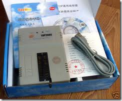
TOPWIN Universal Programmer

TOPWIN Universal Programmer is a cool Chinese product that helps you program a wide variety of Eproms,Microcontrollers,EEproms and GAL ICs.

imageimage

I have tested Eproms 27c512, 27c4001 , Microcontrollers AT89s52,Philips 89V51RD2, AT89C2051,ATTiny2313,ATMega16L,EEprom 24c16, 93C46,PIC16F877A, PIC16F676 all devices are unbelievably working fine.All available flash ROMs of Microcontrollers were read, erased and written again with very little effort.

It has also a built in IC tester (TTL logic tester). Just plug standard logic chip (74xx, 40xx, 45xx), select chip type and press test. The working condition of the chip is reported. Also there is an interesting feature called logic searcher. Just insert unknown chip and press’ find’. All possible types of that device is listed.

The only drawback is the poor English of the instruction manual accompanying the product.

Here is the step by step guide of installing and using the TOPWIN Programmer.

First thing is to install the Universal programmer software Topwin.exe that is supplied with the programmer.The latest version6.3.1 installs fine on Windows 7 OS. After successful installation the Topwin icon appears on your desktop.

Image 3

If the icon does not appear go to All programs ,right click on Topwin6 and click ‘send to’ and then select ‘Desktop(create shortcut)’.

Now connect the Topwin programmer to the USB port of your PC using the usb cable provided with the device.

image

The red led glows indicating power is ON to the programmer.Now double click the Topwin icon on your desktop to start the program.

Caution : First connect the device to the Usb port and after the power Led lights up then start the Topwin program.If you start the program and then  try to connect the device to the Usb port, the program will CRASH.

The main window appears like

Image 2

Image 3

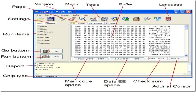
Like any other software ,on the top appears the MENU bar with dropdown functions.

Below the menu bar you can see a strip of image icons forming the TOOL bar.

Image 4

The icons from left to right enables following functions

Load file to buffer  ,  Save buffer to file  , Select Chip , Erase Chip , Check Blank Chip , Write code to chip , Compare chip with the file buffer , Write config. to chip , Read config. to chip , Lock chip , Read chip to buffer , Display Mfa & type , Change Language.

If you hover the mouse over any icon , the respective function is displayed as tooltip.

In the center you can see 3  tags Buffer,Config and Placement

Image 5

When you click Buffer you can view the buffer memory of the programmer .This is the place where you ‘Read’ data of chip into.You can save this buffer data to a file and later reload the file so that you can copy the data on to another chip.

Config is the place where you define the Address space of Chip start ,Chip end,Buffer start location and delay time of buffer loading.

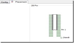
Placement  is another important tag where you can find the position of IC .According to this diagram , you have to the place the IC in the holder.Take note of  the tiny cut like notch in the IC and place the IC carefully into the holder as per the diagram shown.The position of placement changes for different ICs.Some ICs need to be placed in the center of the  holder.

To the left of the main window is the Operation window with 2 tags ,Run & Settings .At the bottom of the operation window  are two large buttons  GO & RUN

Now let me explain the operation of copying an EPROM 27c512 of ST make loaded with some program.

Step1:

To begin with connect the programmer to the USB port of your PC or Laptop and then start the Topwin program.

Step2:

Now select the chip you want to program, in this case Eprom 27c512 ST make, by clicking the third icon from left or  from menu Run –> Select chip tree

Image 9

Select EPROM –> ST  -> 27c512 –> ok   i.e., Type of Device->Device Make->Device No.

The green LED glows indicating that the device is Ready.

Step3 :

Now click the placement tag to see how to place the IC in the holder.

Image 6

It shows that 27c512 has to be placed with ‘cut’ side of IC downwards.Place the IC accordingly and lock the handle of the ZIF socket (Zero Insertion Force socket, it is called so ,as you are applying zero force to insert an IC).

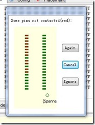
If you place wrongly, then a dialog pops up informing that connections are wrong.

Image 10

Step 4:

To Read the contents of Eprom into the buffer click Run –> Read or click the last but third icon in the tool bar.Now you can see the buffer window populated with data from your Master IC 27c512.

Remove the Master IC and then place an empty IC in the same position you placed the master.

Step 5:

Click  ‘Write code to chip’ icon ,sixth icon from left.The data in the buffer is written to your new chip.Now you have a copy of the Master Eprom .

You can click from the top menu Run – > Verify to verify the copy operation.

At the bottom right of the buffer window the SUM  of data of the master Eprom is displayed.This Checksum can be compared with that of copied ones to confirm whether the copied data is correct.

If you want to make a number of copies then click RUN button of operation window.The programmer will automatically copy and then informs you to place a new chip. In this case the operations like Blank,Write,Verify where you have placed tick marks in the operation window, takes place automatically.

Image 8

Step 6:

If you want to save the buffer then click File –> Save Buffer and provide a name.The file will be stored as a binary file with  .bin extension.

To clear the buffer click Edit –> Fill Buffer  –  ok

Please note that an Eprom can be erased only under the exposure to Ultra Violet light for few minutes and you can’t erase it with this programmer.

Also note that,  Eprom ICs require around 12.5v to enable fusing.The programmer has a built in voltage Doubler and regulator to boost the USB 5v supply to meet the requirement of fusing Eprom.If the Eprom requires more than 500ma of current ,then that type of Eproms cannot be programmed with  Topwin.

Programming  ATMEL 89S52

To program the microcontroller AT89s52 you have to load the buffer with .hex file.The hex file is created through Microvision KEIL development software.Generally for ATMEL controllers coding is done in embedded C in KEIL IDE and finally it provides the Intel format .hex file (more on this in future posts).

Start the Topwin program.

File –> Open and then browse to the location where you have stored the .hex file and select it.

A file format dialog box opens with automatically showing the type of file you have selected (in this case  .hex file).Just click Ok.The Hex file is loaded to the buffer.

Before clicking the Run button check for the tick marks under Run tag.

By default all process like Erase,Blank,Write,Verify add Security are tick marked which will be executed one by one automatically.Security is  a LOCK to the code so that no body can make a copy of your master chip.

The process is similar to program a PIC microcontroller except that you will arrive at the .hex file through MPLAB IDE.


For availability of this programmer please contact

Saravana Electronics,

10,Edayar Street,Coimbatore – 641001

ph : 91422 2398827

alselectro@gmail.com