The main & first part of your embedded project is creation of .HEX file from the C or Assembly code.For 8051 devices KEIL MICROVISION is a well known IDE .
The free version of KEIL has a limitation of 2k code size. Programs that generate more than 2 Kbytes of object code will not compile, assemble, or link in the free version.
This software is an integrated development environment (IDE), which integrates a text editor to write programs & a compiler which converts your source code to hex file.This HEX file is then fused on to the target chip.
The free version can be downloaded from :
https://www.keil.com/demo/eval/c51.htm
Install the downloaded KEIL software & open it.
The IDE is simple with 3 windows : Project Workspace , Editing Window & the Output window
Before starting with your new project , create a folder for your project. For this e.g we create a folder F:\blinkled
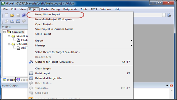
Click on Project – > New uvision project & browse to the location of the folder we created in F:\
Provide a filename as “blinkled” & click on Save.
Device selection window opens automatically. Select the target device as AT89S52 & click OK.
Confirm with YES button on the next screen.
You can see the TARGET1 created under the Project space.
Right Click on that Target1 & select Options for Target
A new Options window opens.Click on the OUTPUT tab .Tick mark against “Create Hex File “.
If you forget to check this option , you will not find the HEX file in the project folder after a Build.
Click OK to close the Options window.
To add the .C file Right click on Source Group1 under Target1 & click on “ Add New item to Group”
On the next screen select the first option C File ,provide a name & click on ADD.
Now your .c file is added to the Source Group.
Enter the following code in to the Editor window.
This sample code makes the LED connected to port pin P1.0 BLINK .
————————————–
// Program to blink an LED at Port pin P1.0 (physical pin 1 of IC)
#include<reg52.h> // special function register declarations for 89s52
#include<stdio.h> // prototype declarations for I/O functions
sbit LED = P1^0; // defining pin P1^0 as LED
void delay(void) ; //delay function prototype declaration
void main (void)
{
LED = 0 ; // Make LED pin as Output
while(1) //indefinite loop
{
LED = 0; // LED Off
delay();
LED = 1; // LED ON
delay();
}
}
void delay(void)
{
int j;
int i;
for(i=0;i<10;i++)
{
for(j=0;j<10000;j++)
{
}
}
}
—————————————————–
After entering the code click on the SAVE icon .Now the * mark will vanish on the main.c file.
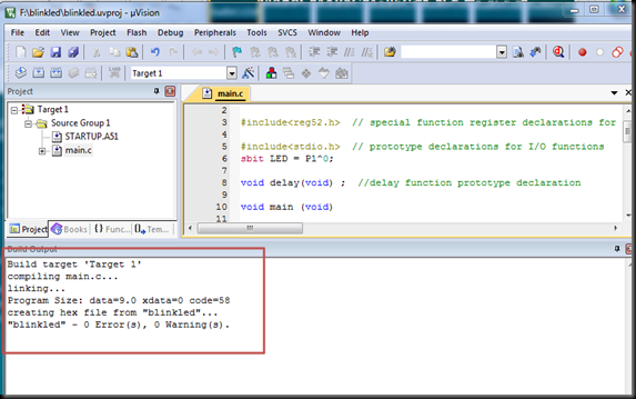
Press F7 or click on the BUILD button to start compiling the code.
If there is no syntax error , a HEX file is created inside your project folder.
This .HEX file has to be fused on to the Target chip using the ISP programmer & PROGISP software.
This Fusing procedure is explained in the next post.
SIMULATION :
KEIL’s inbuilt Debug can be used for Simulation of the code , without any physical Hardware.
Click on Debug – > Start/stop Debug session.
Now your project workspace window shows most of the SFRs as well as GPRs r0-r7. Also one more window “Watches “ is now open. In this window you can see different variable values.
To add variable in watch window goto "watch#1" tab. Type F2 to edit and enter the name of your variable .
To see the output on ports ,under Peripherals—> select I/O ports – > Port 1.
You can give input to port pins by checking or unchecking the check box. here the check mark means digit 1 and no check mark means 0. The output on the pin will be shown in same manner
To run the program you can use any of the option provided "go", "step by step", "step forward", "step ove" etc.
Press F5 to start simulation .The port pin 1.0 starts blinking to show the result.
Click on Debug – > Stop to Exit simulation.


