Video :
In the previous post we explored the ways of uploading code on to STM32 using UART1 & Serial Wire Interface.
Its also possible to upload code through USB port of STM32. By default Bluepill modules are not shipped with boot loader. To enable USB uploading we need to flash a bootloader.
This post is related to USB uploading on to an Arduino core Bluepill.
Firmware (.bin file) for bootloader can be flashed only through UART1 of STM32
USB-TTL module built on CP2102 is used for this purpose.
Connection details as below :
PA9 Tx to Rx of USB-TTL
PA10 Rx to Tx of USB-TTL
5v to 5v , GND to GND
Plug in the USB-TTL module to PC after installing the CP2102 driver
https://www.silabs.com/products/development-tools/software/usb-to-uart-bridge-vcp-drivers
A port will be allotted to the module.
On STM32 Bluepill shift the BOOT 0 jumper to 1 position & press Reset button.
Before proceeding , collect the following Software tool , driver & .bin file
https://github.com/rogerclarkmelbourne
Firmware .bin file can be downloaded from Roger Clark’s github. Ensure to download the bin file with suffix _pc13,bin , as the built in LED of our module is mapped to PC13.
Flasher tool can be downloaded from :
https://www.st.com/en/development-tools/flasher-stm32.html
Install the Flasher tool
Note the install location of the tool & create a shortcut manually.
Start the Flash Loader software.
The UART port is automatically detected .
Click next.
If you get an Error saying No Response from Target , ensure that BOOT 0 jumper is placed on 1 position & start the flash loader again.

Now the Target is readable. Click Next.
Target Device is automatically detected.Click Next.
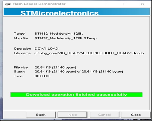
Select Download to Device & browse to location of .bin file.
Now the boot loader is installed successfully.
Now replace the BOOT0 jumper back to 0 position & then remove
USB-TTL module.With power on position , the Boot 0 jumper must be set back to 0.
Connect the usb of STM32 to that of PC.
Open Device manager.
Under Ports you may see an exclamation mark or just a USB serial device.
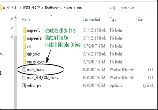
Related driver should be installed , so that it shows Maple Serial COM port.
You can download the driver here :
Just Double click the install_drivers batch file .
Now you can see Maple Serial COM port under Device Manager.
Open the Arduino IDE.
Select Board as Generic STM32F103C Series.
Select Upload method as STM32duino bootloader.
Select the Maple Port
Now upload the blink sketch ( with LED_BUILTIN defined as PC13)
There is no need to shift BOOT0 jumper to upload code.Directly through USB you can do the upload.
With some PCs you may get upload done , but the USB port resets before starting to function with the newly uploaded code.
This is caused by the faulty R10 value resistor seen back to the board.
Most PC USBs accept this pull up value.But sometimes you get the Reset error.
The Blue Pill has design fault as it uses a 10k USB pull up resistor, but the USB spec requires 1.5k
You can remove the smd resistor R10 & replace with a 1.5k resistor.
Or simply solder a 1.8k resistor between PA12 & 3.3V , if you cannot handle SMD component.


Hi can you give me hint why the board wont showup on linux port selection on Arduino (/dev/ttyACM0)
it’s only show me this device id
Bus 002 Device 086: ID 1eaf:0003
while it usb device id should changed to 0004 after few seconds from boot