VIDEO Demo :
Relay module boards play an important role in Home automation projects. Generally we connect the load ( fan,light,etc…) to be controlled through the Relay contacts . While is the relay is controlled ON/OFF , IN TURN the load is controlled through the relay contacts.
Different types of relay modules are available .
In this post we explore the best Relay module suitable to use with Raspberry PI.
Relay modules are available in 12v & 5v .The best one for RPI is 5V Relay Module with Opto coupler drive.
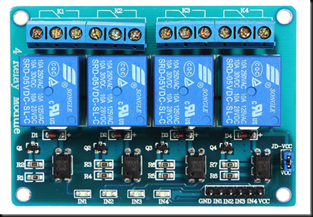
This type of relay boards have opto coupler & NPN transistor to control the relays. Each relay is controlled by an opto+transistor combInation.
When a LOW is applied to INPUT , say IN1 , the photo diode inside optocoupler conducts which in turn activates the photo transistor inside the opto.
The NPN TRANSISTOR after the opto coupler is triggered which in turn switches ON the relay.
On board a Jumper is provided between JD_VCC & Vcc .While the jumper is ON & Vcc is provided with 5v , the board operates normally. When LOW is at input , the relay is ON. The problem arises when connected to RPI whose GPIO pins are at 3.3v level.
When a HIGH is applied from RPI , THERE WILL BE POTENTIAL DIFFERENCE OF 5V – 3.3V = 1.7V which causes the board relay to chatter or malfunction.
So while using with Raspberry PI always remove the jumper & provide 5V to JD_VCC & 3.3V to Vcc.
Both these voltages can be directly connected from the RPI itself. No separate power source required for Relay board. In RPI 3.3V is capable of only 50 milli amp sourcing current.
This 3.3v is connected to Vcc of Relay board which drives only the photo diode of opto coupler.So a small current is enough.
The 5V rail of RPI is capable of sourcing much more current. It depends on the power adapter used for RPI less the current consumed by the RPI itself . 500MilliAmps can be easily sourced at this 5v point of RPI.
Let us now connect PI with 4 channel relay board.
RELAY BOARD RPI
JD_VCC 5v
VCC 3.3V
IN1 Pin 32
GND GND
Ethernet cable is connected between PC & RPI,& PI is accessed from PC through SSH client PUTTY
Refer my previous blog on how to access PI from PC
LOG IN using default user name pi &password raspberry
To test python commands start the python interpreter by typing command
python3
By default, Raspbian Stretch version uses Python 2. However, versions 2 and 3 come installed by default. We just have to make 1 minor change so that the Pi uses Python 3 whenever we type python into a terminal.
In a terminal window, enter the following command:
nano ~/.bashrc
Scroll down to the bottom, and add the following command to the file:
alias python=’/usr/bin/python3′
Exit out of nano by pressing ctrl+x, press the y key when prompted if you want to save the file, and press the enter key.
you can run the contents of the .bashrc script by entering:
source ~/.bashrc
Now check the version of Python
python –version
Just type in python to get the INTERPRETER symbol >>>
Now you can test python commands one by one.
First import RPi.GPIO module
import RPi.GPIO as GPIO
Functions are called Modules in Python. Note the casing of letters used RP in capitals & i in small case .We also use alias name GPIO , so that further in code you just need to mention GPIO instad of RPi.GPIO
To specify which pin configuration you are using type
GPIO.setmode(GPIO.BOARD)
There are two ways of numbering the IO pins on a Raspberry Pi within RPi.GPIO. The first is using the BOARD numbering system. This refers to the pin numbers on the P1 header of the Raspberry Pi board. The advantage of using this numbering system is that your hardware will always work, regardless of the board revision of the RPi. You will not need to rewire your connector or change your code.
The second numbering system is the BCM numbers. This is a lower level way of working – it refers to the channel numbers on the Broadcom SOC. You have to always work with a diagram of which channel number goes to which pin on the RPi board. Your script could break between revisions of Raspberry Pi boards.
To detect which pin numbering system has been set (for example, by another Python module):
mode = GPIO.getmode()
The mode will be GPIO.BOARD, GPIO.BCM or None
Physical pin 32 is set as OUTPUT using
GPIO.setup(32,GPIO.OUT)
Pin 32 is initially made HIGH so that relay is OFF
GPIO.output(32,GPIO.HIGH)
To make the Relay ON , set pin 32 to LOW
GPIO.output(32,GPIO.LOW)
At the end any program, it is good practice to clean up any resources you might have used.
To clean up at the end of your script:
GPIO.cleanup()
Note that GPIO.cleanup() also clears the pin numbering system in use.
Now let us connect other Relay inputs to RPI
PIN 36 to IN2
PIN 38 to IN3
PIN 40 toIN4
Open NANO editor by typing
sudo nano relay.py
Feed in the following code.
Note the usage of Indentation for try block.
You can press TAB key to introduce blank space indentation whichis equal to braces in PYTHON.
——————————————
import RPi.GPIO as GPIO
import time
GPIO.setmode(GPIO.BOARD)
GPIO.setup(32,GPIO.OUT)
GPIO.output(32,GPIO.HIGH)
GPIO.setup(36,GPIO.OUT)
GPIO.output(36,GPIO.HIGH)
GPIO.setup(38,GPIO.OUT)
GPIO.output(38,GPIO.HIGH)
GPIO.setup(40,GPIO.OUT)
GPIO.output(40,GPIO.HIGH)
# main loop
try:
GPIO.output(32,GPIO.LOW)
print "First Reay ON"
time.sleep(2)
GPIO.output(36,GPIO.LOW)
print "Second Relay ON"
time.sleep(2)
GPIO.output(38,GPIO.LOW)
print "Third Relay ON"
time.sleep(2)
GPIO.output(40,GPIO.LOW)
print "Fourth Relay ON"
time.sleep(5)
GPIO.cleanup()
print "Good bye!"
except KeyboardInterrupt:
print(“QUIT”)
GPIO.cleanup()
————————————————
Press CTRL+X to quit & press Y to save the file.
To execute the file
python relay.py
The Relays will be switched ON one by one & finally all Relays will be OFF , according to code.
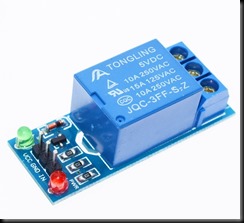
The single channel relay boards are different. Some boards have OPTO Coupler & some
do not have opto.
The board with opto is HIGH enabled. A HIGH is required at IN to switch ON relay.
The board without OPTO is LOW enabled . A LOW is applied at IN to switch ON Relay.
Jumper is not seen on these single relay boards.
Always use 3.3v to Vcc in these single channel relay boards.


I want to give my congratulations and gratitude for the effort made by all of us, the truth that this special work is time consuming , but we know that I enjoyed it a lot and follow its success, then in another mail I am going to pose a small problem that I found when using an arduino, so that he has the kindness to help me a greeting and that this very well.
Sent from my MetroPCS 4G LTE Android Device
Hi, Nice explanation! I got single Tongling 5V relay and troubles with Pi connection. I used 5V into VCC but it was not working correctly! Then I switch to 3,3V – VCC and put high/low on IN and it was switching exactly like you stated in the last sentence! But why it works with 3,3V-VCC while it is designed for 5v as written on the relay? 🙂 And you say: it should be always 3,3V for single relay. I saw some mods for Tongling relay to work on 5v but it was too complex to apply resistors etc.. while it is working fine on 3,3V…..