In the previous post we’ve seen the LED blinking program.In this post we shall see how to connect a push switch to a Digital Input of PIC 16F877A .
A micro switch is connected between port pin RB0 & Ground. Port pin RB0 is pulled High through a 10k resistor connected to +5v supply.On pressing the switch the LED glows & on releasing the switch the LED GOES Off.
In the development board I’ve used , the pull up resistors are not provided.But this can be enabled internally by making the bit RBPU=0 of Option Register.
This can be achieved by declaring
OPTION_REG=0b01011110;
or RBPU=0; The NOT_RBPU bit (MSB) is cleared in the Option Register to apply PULL UP internally to all PORTB pins.
The pull up resistor is mandatory to avoid floating values at digital inputs.
Following 10 Steps are common for all projects except the project name is different.
In future projects I will not mention the following 10 steps .These are the initial settings required for each project.Future posts will be focused on main C code straight away.
——————————————————————————-
STEP 1 :
Click on File –> New Project
Under Choose Project select category “Microchip Embedded “ & Projects as“ StandaloneProject “
STEP 2 :
Select the Target device as PIC16F877A.
Click Next
STEP 3 :
Select the TOOL as PICKIT2
STEP 4 :
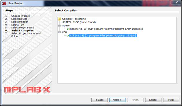
Select the Compiler as XC8 & click Next.
STEP 5 :
Provide a name to the project & select the Project folder to store the results.
Click on FINISH
STEP 6 :
Project folder appears in the File pane.
Right click on Source Files & select New –> C Main File
STEP 7 :
Provide a name to the C file .The extension must be selected as c from the drop down below.
Click on FINISH
STEP 8 :
Click on Window –> PIC MEMORY VIEWS –> Configuration Bits
On the Task pane window you get the Configuration Bits .
Each bit can be modified as ON or OFF by the drop down menu following the bit
Set FOSC to HS for High Frequency External oscillator & other bits all OFF.
Click on “ Generate Source code to Output” button at the bottom.
STEP 9 :
Configuration bit setting code is generated.
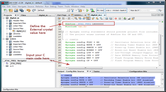
Delete the default code seen in the Editor pane on top.
Now Paste the Configuration code here.
STEP 10 :
Finally add the Crystal Frequency definition to the top of #include <xc.h> statement
#define _XTAL_FREQ 16000000
——————————————————————————-
——————————————————————————-
Now you can feed the following C main code below the configuration code.
OPTION_REG MSB bit is cleared to enable internal PULL UP Resistors for PORTB.
Port B pin 0 is declared as INput where switch is connected
Port D Pin 2 is declared as Output where LED is connected .
Initially LED is OFF by making RD2 pin low (RD2=0).
Under the never ending loop the condition of RB0 is verified & if the switch is pressed RD2 is made High , thus making the LED glow.
After a delay of 2 secs the LED is made OFF.
After feeding the Code press CTRL+SHIFT+S to save all the project files.
Now click on RUN –> Build the Main Project
After getting BUILD SUCCESSFUL click on “Run Main Project “
The generated HEX file will be loaded on to the Target chip .
If you press the switch at RB0 the LED at RD2 glows.
The same code can be used to check the Buzzer circuit & the Relay circuit ( if you’ve purchased the development board shown above)
Remove the wire at LED point & connect it to Relay input (connector CN12 ) which is seen near the yellow sugar cube relay on top right of the board.Now by pressing the switch the relay gets ON ,just like the LED.
To test the buzzer , connect the wire from RD2 port pin to CN21 .The buzzer is with a white round sticker on its top , seen just above the LCD.Pressing the key will activate the buzzer now.
For availability of this development board contact :


