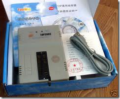
TOPWIN Universal Programmer is a cool Chinese product that helps you program a wide variety of Eproms,Microcontrollers,EEproms and GAL ICs.
I have tested Eproms 27c512, 27c4001 , Microcontrollers AT89s52,Philips 89V51RD2, AT89C2051,ATTiny2313,ATMega16L,EEprom 24c16, 93C46,PIC16F877A, PIC16F676 all devices are unbelievably working fine.All available flash ROMs of Microcontrollers were read, erased and written again with very little effort.
It has also a built in IC tester (TTL logic tester). Just plug standard logic chip (74xx, 40xx, 45xx), select chip type and press test. The working condition of the chip is reported. Also there is an interesting feature called logic searcher. Just insert unknown chip and press’ find’. All possible types of that device is listed.
The only drawback is the poor English of the instruction manual accompanying the product.
Here is the step by step guide of installing and using the TOPWIN Programmer.
First thing is to install the Universal programmer software Topwin.exe that is supplied with the programmer.The latest version6.3.1 installs fine on Windows 7 OS. After successful installation the Topwin icon appears on your desktop.
If the icon does not appear go to All programs ,right click on Topwin6 and click ‘send to’ and then select ‘Desktop(create shortcut)’.
Now connect the Topwin programmer to the USB port of your PC using the usb cable provided with the device.
The red led glows indicating power is ON to the programmer.Now double click the Topwin icon on your desktop to start the program.
Caution : First connect the device to the Usb port and after the power Led lights up then start the Topwin program.If you start the program and then try to connect the device to the Usb port, the program will CRASH.
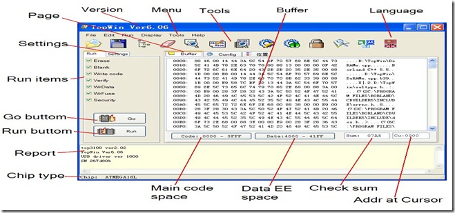
The main window appears like
Like any other software ,on the top appears the MENU bar with dropdown functions.
Below the menu bar you can see a strip of image icons forming the TOOL bar.
The icons from left to right enables following functions
Load file to buffer , Save buffer to file , Select Chip , Erase Chip , Check Blank Chip , Write code to chip , Compare chip with the file buffer , Write config. to chip , Read config. to chip , Lock chip , Read chip to buffer , Display Mfa & type , Change Language.
If you hover the mouse over any icon , the respective function is displayed as tooltip.
In the center you can see 3 tags Buffer,Config and Placement
When you click Buffer you can view the buffer memory of the programmer .This is the place where you ‘Read’ data of chip into.You can save this buffer data to a file and later reload the file so that you can copy the data on to another chip.
Config is the place where you define the Address space of Chip start ,Chip end,Buffer start location and delay time of buffer loading.
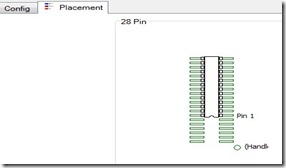
Placement is another important tag where you can find the position of IC .According to this diagram , you have to the place the IC in the holder.Take note of the tiny cut like notch in the IC and place the IC carefully into the holder as per the diagram shown.The position of placement changes for different ICs.Some ICs need to be placed in the center of the holder.
To the left of the main window is the Operation window with 2 tags ,Run & Settings .At the bottom of the operation window are two large buttons GO & RUN
Now let me explain the operation of copying an EPROM 27c512 of ST make loaded with some program.
Step1:
To begin with connect the programmer to the USB port of your PC or Laptop and then start the Topwin program.
Step2:
Now select the chip you want to program, in this case Eprom 27c512 ST make, by clicking the third icon from left or from menu Run –> Select chip tree
Select EPROM –> ST -> 27c512 –> ok i.e., Type of Device->Device Make->Device No.
The green LED glows indicating that the device is Ready.
Step3 :
Now click the placement tag to see how to place the IC in the holder.
It shows that 27c512 has to be placed with ‘cut’ side of IC downwards.Place the IC accordingly and lock the handle of the ZIF socket (Zero Insertion Force socket, it is called so ,as you are applying zero force to insert an IC).
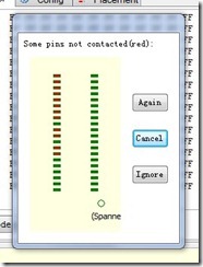
If you place wrongly, then a dialog pops up informing that connections are wrong.
Step 4:
To Read the contents of Eprom into the buffer click Run –> Read or click the last but third icon in the tool bar.Now you can see the buffer window populated with data from your Master IC 27c512.
Remove the Master IC and then place an empty IC in the same position you placed the master.
Step 5:
Click ‘Write code to chip’ icon ,sixth icon from left.The data in the buffer is written to your new chip.Now you have a copy of the Master Eprom .
You can click from the top menu Run – > Verify to verify the copy operation.
At the bottom right of the buffer window the SUM of data of the master Eprom is displayed.This Checksum can be compared with that of copied ones to confirm whether the copied data is correct.
If you want to make a number of copies then click RUN button of operation window.The programmer will automatically copy and then informs you to place a new chip. In this case the operations like Blank,Write,Verify where you have placed tick marks in the operation window, takes place automatically.
Step 6:
If you want to save the buffer then click File –> Save Buffer and provide a name.The file will be stored as a binary file with .bin extension.
To clear the buffer click Edit –> Fill Buffer – ok
Please note that an Eprom can be erased only under the exposure to Ultra Violet light for few minutes and you can’t erase it with this programmer.
Also note that, Eprom ICs require around 12.5v to enable fusing.The programmer has a built in voltage Doubler and regulator to boost the USB 5v supply to meet the requirement of fusing Eprom.If the Eprom requires more than 500ma of current ,then that type of Eproms cannot be programmed with Topwin.
Programming ATMEL 89S52
To program the microcontroller AT89s52 you have to load the buffer with .hex file.The hex file is created through Microvision KEIL development software.Generally for ATMEL controllers coding is done in embedded C in KEIL IDE and finally it provides the Intel format .hex file (more on this in future posts).
Start the Topwin program.
File –> Open and then browse to the location where you have stored the .hex file and select it.
A file format dialog box opens with automatically showing the type of file you have selected (in this case .hex file).Just click Ok.The Hex file is loaded to the buffer.
Before clicking the Run button check for the tick marks under Run tag.
By default all process like Erase,Blank,Write,Verify add Security are tick marked which will be executed one by one automatically.Security is a LOCK to the code so that no body can make a copy of your master chip.
The process is similar to program a PIC microcontroller except that you will arrive at the .hex file through MPLAB IDE.
For availability of this programmer please contact
Saravana Electronics,
10,Edayar Street,Coimbatore – 641001
ph : 91422 2398827


w78e365a microcontroller is contactable with any universal programmer of topwin .please give me an answer.
The Nuvoton IC W78E365A is similar to 89S52 & supports In System Programming.
Or try ELNEC device programmer.As I’ve not used this IC I don’t have much info.
can it work with 93s56?
Yes it should work.93S56 is in the list of working ICs.
can we change the programs of all the dvd player ics?
TOPWIN supports DVD ICs of family EON e.g.. EN25F80
I used Mikroc to write the a program for PIC16F877A, and made a .HEX file. My question is, how can i set the config tab(Beside the buffer tab) ? Another question is, do i need to check the “Write data” in addition to “Write” for this Micro-controller ? Thank you.
Config file is like setting Fuses as in AVR ICs.You can set the Config for FOSC as external RC clock ,WDTEN – Watch dog,PWRTE & others.Please refer the PIC IC data & change config only if you need.
To write on Flash memory you need to check “Write”. WrData is to write data on EEPROM memory.
Thank you very much. Appreciate it.
can I program PQFP 89S52 using ISP cable from programmer to my hardware?
TOPWIN programmers do not support ISP .Quad Flat ICs can be programmed using Programming adapters & plugging on to ZIF socket.
If you’re particular about In System Programming try ELNEC BeeProg Universal Programmer.
Pls where can I get the software, I mean download it online…pls I will appreciate download link….
Download the TOPWIN6 program from my Skydrive here
https://skydrive.live.com/?cid=6512B4A300B9A544&id=6512B4A300B9A544!105
top win is not working on my 64 BIT WINDOW 7 HOME BASIC… Help me out ??
You’ve to disable Device driver signature enforcement for TOPWIN to work on 64bit.
Follow the steps as in http://tinyurl.com/8llxkhe
is this burner also burn atmel atmega8a controller
Yes,It supports all AVR ICs.
When i load a hex file the software gives me three options:-
No clear
Fill by 00
Fill by FF
And the Fill by FF is selected by default should i change this option or its ok??
I have to program pic 16F877A
You can leave it for default FF. It will fill up all empty spaces with FF while fusing the .HEX file
Glad to read You posting
hello sir
i am using topwin programmer but i have a problem . installation was ok but it is not finding the programmer model . please guide me how to find programmer model and what is the problem .
plz sir reply fast because i am suffering with rhis problem a long time ago and i need it urgently.
Topwin has some issues with Win 8 OS.On Win7 you should get “Jungo – >TOPUSB1” under Device manager as soon as you connect the hardware to PC.If not detected , try to reinstall Topwin program by downloading from
http://tinyurl.com/p4ql422
HELLO
I have a problem:
I get “Jungo – >TOPUSB1″ but when i open topwin6 i get “USB error”. I use window 7 Home Premium 64bit. I already disable Device driver signature enforcement.
HELP ME! Thanks
Try reinstalling Topwin as Administrator.Also from Tools — > BackCheck Programmer from within Topwin IDE check whether you get Programmer OK.
Hello
I have a problem, i am using topwin programmer 2008, i use it on windows 7 32 bit, when i programming the PIC16F84A in the (Write) the programming operation stuck for 2-3 second and then completed (Write complete) ,but when i test the PIC it dose not respond….thanks..
Try 16F88 which has same config as 84.PIC16F84 is obsolete and may be defective ones available in market.
I am using Win 7 ultimate. In that top win 6 installed when i program with pic16f877a program verify error occur . How can i Solve this.
Check whether TopUsb is showing under DeviceManager.Generally program verify occurs while Hex file is corrupted.Try fusing a basic LED blinking hex code & confirm
I have win8 ,64 bit and top 2009 programmer don’t work with win 8 what can I do sir .m
Topwin2008,9 has issues with WIN8 64bit.You can try disabling Windows driver signature verification feature.Follow this link which is similar to the one you needed.
If you get problems again,you’ve to either change your OS to Win7 or go for Topwin 2013 or 3000 model for which you get a new upgraded software here :
http://www.topwin6.com/tops/TopWin_Ver7.rar
Hello
can i burn pic-16f88 (18 pin) using topwin6 universal burner
Yes you can.Select the chip as PIC16F84A & proceed. 16f88 is not listed in Topwin.
Dear Sir,
Did you mean that by selecting the microchip pic 16f84A in topwin6 i can program pic 16f88
hello
by selecting the microchip pic 16F84A in topwin6, can i burn program on pic 16F88
Hello
I just bought a top2008 programmer. The cd includes topwin6 and I have Windows7 64 bit. I tried disabling Windows driver signature verification base on the comments above but “Reload USB Driver” always show everytime I run topwin6.
I have rebooted my laptop many times, tried also installing & uninstalling topwin6.
Please help me out. Thank you.
Uninstall Topwin & try reinstalling with admin rights.Install to C:\topwin & do not change the target.Use the USB cable that is supplied alongwith the unit.As you’ve disabled driver signature verification , no other step required.The drivers should get installed automatically along Topwin6.The programmer has got issues with Win8 64 bit.On Win7 64 bit it should work fine.
I don’t know what I had done, my USB ports are not working anymore, even my fingerprint scanner is not working. Also I tried your advice but also did not work. The default during installation is C:\Top. Hope I can get this working with your help.
I already got it working. Shutdown my pc for about 5 minutes and my USB ports is working again. I installed virtual box 32bit XP and programmer is working. The disadvantage I found is my laptop becomes slower.
Im seeking for device but thr is not available in many electronic showroom pls help me to get it
You can buy online here:
http://www.alselectro.com/universal-programmers.html
Topwin does not work on Windows8 .Consider buying MINIPRO programmer.You can see the video demo on the above link.
i have lost CD… from where can i get the softwer..
Download from this link :
http://www.topwin6.com/Topwin6.rar
i have topwin 2009 programmer,lost her programming cd from where down lode it ,and its works or not windows 7 32 bit,
Can I use this software(TOPWIN 2011) in Windows 8
HI sir i was facing a problem when ever i am trying to dump the hex its shows
Write error